EasyManua.ls Logo

Eliwell IC 915 User Manual

Eliwell IC 915
10 pages
To Next Page IconTo Next Page
Page #1 background imageLoading...
Page #1 background image
BUTTONS AND MENUS ACCESSING
AND USING MENUS
The resources are arranged in a menu that
can be accessed by pressing and quickly
releasing the “set” button (Machine Status
menu) or holding down the “set” button
for more than 5 seconds (Programming
menu).
To access the contents of each folder indi-
cated by the relevant label, just press the
“set” button once.
You can now scroll through the contents
of each folder, modify it or use its func-
tions. If you do not use the keyboard for
over 15 seconds (time-out) or if you press
the “fnc” button once, the last value
shown on the display is confirmed and you
are taken back to the previous screen
mask.
MACHINE STATUS MENU
(See Machine Status Menu Diagram)
To access the Machine Status menu, press
the “set” button and quickly release it.
The “SP1” label appears.
(If alarms are active, with the exception of
faulty probes/probe errors, the “AL” label
appears).
By using the “UP” and “DOWN” buttons
you can scroll through the other folders in
the menu: the folders are indicated below
in the order they appear:
-SP1: Set point 1 setting folder or
-AL: alarm folder (if alarms present, with
exception of faulty probes/probe errors);
-SP2: Set point 2 setting folder.
-Pb1: probe 1 value folder;
-Pb2: probe 2 value folder;
The folders are present according to
the presence and configuration of the
associated resource.
Alarm on
If an alarm condition exists when the
Machine Status menu is accessed, the “AL
folder label appears (see “Diagnostics”
section).
USER INTERFACE
The user has a display and four buttons
for controlling instrument status and pro-
gramming.
IC 915 (LX)
electronic controller with 2 set points and differential set point
adjustment
cod. 9IS23071
rel. 12/04
GB
Alarm
•ON for active
alarm;
•blinking when
a silenced alarm
is still present
out2
Relay 2 (OUT2)
ON for relay on
(energized);blin
king for protec-
tion delay or
enabling
blocked
out1
Relay 1 (OUT1)
ON for relay on
(energized);blin
king for protec-
tion delay or
enabling
blocked
Soft Start
ON when Set
point is being
set
(and Set point
setting)
blinking when
Soft Start func-
tion is on
Set-point/
Reduced set
point
•ON to modify
Set-Point;
•blinking when
reduced set
point is entered
set
f nc
IC915LX
out 2
out 1
AL
SP1
SP2
set
alarms
value SP1
value SP2
set
set
set
change
SP1(2) value
show alarms
is present
press and release
(quickly/single press)
if alarm(s)
present
Pb1
Pb2
value Pb1
value Pb2
set
set
is present
MACHINE STATUS MENU DIAGRAM
LEDs
out2 out1
Scrolls through the menu items UP button
Increases the values
Parameter programmable
(par. H31)
DOWN button
Scrolls through the menu items
Decreases the values
Parameter programmable
(par. H32)
fnc button ESC function (quit)
Parameter programmable
(par. H33)
Set point button 1-Accesses Machine Status Menu
(SET POINTS, ACTIVE ALARMS,
PROBE READING) and labels/values;
1-Accesses Programming Menu
(PARAMETERS, COPY C ARD) and
relative labels/values;
3-Confirms commands
fnc
set
Question and Answer IconNeed help?

Do you have a question about the Eliwell IC 915 and is the answer not in the manual?

Eliwell IC 915 Specifications

General IconGeneral
TypeTemperature Controller
DisplayLCD
Output typeRelay
Resolution0.1 °C
Accuracy±0.5 °C
Digital inputs2
Front protectionIP65
Protection ratingIP65
Input typePT100, PT1000, NTC
Power supply24 V AC/DC
Temperature range-50 to +150 °C
Storage temperature-20°C to 70°C

Summary

User Interface and Controls

Interface Overview and Buttons

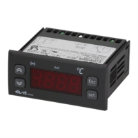
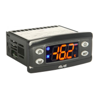
Details the display, four buttons, and menu navigation for status and programming.

LED Status Indicators

Explains the meaning of various LEDs indicating alarm, output status, and set point.

Machine Status Menu Diagram

Visual guide for navigating the Machine Status Menu (SP1, AL, SP2, Pb1, Pb2).

Parameter Setting and Access

Setting Set Points

Procedure for accessing and changing Set point 1 and Set point 2 values.

Keyboard Locking and Security

Instructions for locking and unlocking the keyboard using the LOC parameter.

Advanced Functions (Soft Start)

Introduction to advanced functions like Soft Start for gradual temperature changes.

Using the Copy Card for Programming

Guide to using the Copy Card for parameter upload and download.

Programming Menu Navigation

Accessing Programming Menu Levels

Explains how to access the Programming Menu and its two levels.

Password Protection for Parameters

Details PA1 and PA2 passwords for accessing level 1 and level 2 parameters.

Programming Menu Diagram

Visual flow diagram illustrating the structure of the Programming Menu.

Advanced Functions and Installation

Periodic Cycle and Auxiliary Input

Description of Periodic Cycle function and auxiliary digital input configuration.

Mechanical and Electrical Installation

Guidance on panel mounting and safety precautions for electrical wiring.

Technical Data and System Connectivity

Overview of technical specifications and Televis System connection.

Differential and Offset Adjustments

Differential Adjustment Methods and Diagrams

Explains differential adjustment logic and provides illustrative diagrams.

Setpoint-Offset Adjustment Methods and Diagrams

Explains offset adjustment logic and provides illustrative diagrams.

Diagnostics and Alarms

Diagnostic Indicators and Alarm Handling

Details alarm signals, indicators, and general alarm management.

Temperature Alarm Configuration

Covers max/min alarms, duty cycle errors, and alarm diagrams.

Alarm Code Table

Provides a table mapping alarm codes to specific fault descriptions.

Controller Parameter Configuration

Controller 1 and 2 Parameters

Lists and describes parameters for Controller 1 (rE1) and Controller 2 (rE2).

Controller 1 and 2 Protection Parameters

Lists and describes protection parameters for Controller 1 and Controller 2.

Soft Start and Periodic Cycle Parameters

Lists and describes parameters for Soft Start and Periodic Cycle functions.

System Configuration Parameters

Alarm and Communication Settings

Details alarm (AL) and communication (Add) parameters.

Display Settings

Lists and describes parameters for display configuration (dis).

General Configuration Settings (CnF)

Lists and describes general configuration parameters (CnF).

Extended Configuration and Utilities

Extended Configuration Parameters (CnF)

Lists and describes further configuration parameters (CnF).

Copy Card Operations

Details Copy Card utility functions: Upload, Download, and Format.

Function Activation and Diagrams

Covers function activation (FnC) and the Periodic Cycle Diagram.

Safety and Compliance

Wiring Diagram

Illustrates terminal connections for 12V and 230V power supply versions.

Usage Conditions and Safety

Defines permitted use, unpermitted use, and general safety precautions.

Disclaimers and Liability

Contains statements on responsibility, residual risks, and document disclaimers.

Related product manuals