EasyManua.ls Logo

Eliwell ID 985 LX User Manual

Eliwell ID 985 LX
14 pages
To Next Page IconTo Next Page
Page #1 background imageLoading...
Page #1 background image
USER INTERFACE
The user has a display and four buttons
for controlling instrument status and pro-
gramming. The device can also be con-
nected to a remote display.
At start-up the instrument performs a
Lamp Test; the display and LEDs flash for a
few seconds to check that they are work-
ing correctly. The instrument has two main
menus: the Machine Status menu and the
Programming menu.
ACCESSING AND USING MENUS
The resources are arranged in a menu that
can be accessed by pressing and quickly
releasing the “set” button (Machine Status
menu) or holding down the “set” button
for more than 5 seconds (Programming
menu). To access the contents of each
folder indicated by the relevant label, just
press the “set” button once.
You can now scroll through the contents
of each folder, modify it or use its func-
tions.
If you do not use the keyboard for over 15
seconds (time-out) or if you press the
“fnc” button once, the last value shown on
the display is confirmed and you are taken
back to the previous screen mask.
REMOTE DISPLAY
This has a display with 3 digits + sign that
displays the parameter programming and
alarm display values on the controller it is
connected to during probe reading.
MACHINE STATUS MENU
(See Machine Status Menu Diagram)
Position Associated function Status
Set point/Reduced set point ON for parameter programming level 2
blinking when reduced set point is entered
(set point ON for setting set point)
Compressor or relay 1 ON for compressor on; blinking
for protection delay or enabling blocked
Defrosting ON when defrosting in progress; blinking when activated
manually or by digital input
Alarm ON for active alarm; blinking for silenced alarm
Fans ON when fan is on
aux ON when auxiliary output is operating
aux
fnc
set
ID985/E LX
aux
set
fnc
UP button
Scrolls through the menu items
Increases values
Activates manual defrosting
(see H31 parameter)
DOWN button
Scrolls through the menu items
Decreases the values
Parameter programmable
(see H32 parameter)
fnc button
ESC function (quit)
Parameter programmable
(see H33 parameter
Set button
Accesses Set point and rtc folder
Accesses the Menus
Confirms the commands
Displays the alarms (if active)
Stores hours/min
cod. 9IS23080
rel. 4/08 -GB-
ID 985/S/E/CK - ID985/E LX
electronic controllers for “ventilated” refrigeration units
ww
ww
ii
ii
tt
tt
hh
hh
RR
RR
SS
SS
44
44
88
88
55
55
oo
oo
nn
nn
bb
bb
oo
oo
aa
aa
rr
rr
dd
dd
((
((
II
II
DD
DD
99
99
88
88
55
55
//
//
SS
SS
//
//
EE
EE
//
//
CC
CC
KK
KK
))
))
aa
aa
nn
nn
dd
dd
rr
rr
ee
ee
mm
mm
oo
oo
tt
tt
ee
ee
dd
dd
ii
ii
ss
ss
pp
pp
ll
ll
aa
aa
yy
yy
BUTTONS AND DISPLAY
if alarm(s)
present
AL
Pb1
Pb2
SEt
set
alarms
Pb1 value
Pb2 value
SEt value
set
set
set
set
change SEt
value
show alarms
if present
press and release
(single press)
Pb3
Pb3 value
set
if present
rtc
set
h00
d00
'00
2 sec
2 sec
set
hours
set
days
set
minutes
se presente
d00= Sunday
MACHINE STATUS MENU DIAGRAM
LEDS
Question and Answer IconNeed help?

Do you have a question about the Eliwell ID 985 LX and is the answer not in the manual?

Eliwell ID 985 LX Specifications

General IconGeneral
BrandEliwell
ModelID 985 LX
CategoryController
LanguageEnglish

Summary

Buttons and Display Overview

UP Button Functionality

Scrolls through menu items, increases values, activates manual defrost.

DOWN Button Functionality

Scrolls through menu items, decreases values, parameter programmable.

Fnc Button Functionality

Provides ESC function and is parameter programmable.

Set Button Functionality

Accesses Set point/RTC, Menus, confirms commands, and displays alarms.

User Interface Navigation

Accessing and Using Menus

Describes accessing menus via 'set' and 'fnc' buttons, scrolling and modifying contents.

Remote Display Functionality

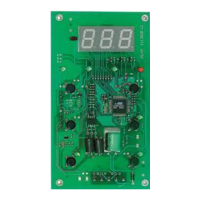
Describes the remote display with 3 digits + sign for parameter programming and alarm display.

Programming Menu Structure

User Level Navigation

Scrolling through user level folders using UP/DOWN buttons.

Accessing Installer Level

Steps to access installer level parameters via 'CnF' and 'PA2' labels.

Installer Level Navigation

Scrolling through installer level folders using UP/DOWN buttons.

Modifying Parameter Values

Process for modifying parameter values using UP/DOWN and SET buttons.

Keyboard and Password Management

Keyboard Locking Mechanism

Facility for disabling the keyboard via key press or 'Loc' parameter.

Password Protection

Limiting parameter access at user/installer level using PA1/PA2 parameters.

Copy Card Functionality

Using the Copy Card

Using the Copy Card for quick programming via upload/download operations.

Manual Defrost Activation

Activating Manual Defrost

Procedure to activate manual defrost cycle by pressing the UP button for 5 seconds.

Advanced Functions

Door Switch Input

Clean contact digital input with programmable polarity for door switch functions.

Link Functionality

Connecting up to 8 instruments (Master/Slave) up to 50m distance.

Echo Repeater

Displays values of associated instrument, acts as a repeater.

Network Defrosting

Network control of defrosting via Master commands, synchronous or sequential.

Other Network Functions

Master activating functions like lights, alarms, auxiliary set points for Slaves.

FnC Function Folder

FnC Folder Functions

Functions available in the FnC folder for programming menu level 1.

Defrost Control

Defrost Start Conditions

Conditions for defrost start based on temperature and parameter H45.

Defrost End Conditions

Conditions for defrost end based on probe values or time-out.

Pressure Switch Input Controller

Pressure Switch Diagnostics

Diagnostics for associated digital input using configuration table.

Condenser Fan Controller

Condenser Fan Operation

Controller associated with probe Pb3 for fan operation.

System Diagnostics and Alarms

Alarm Conditions and Error Codes

Alarm conditions, error codes (E1, E2, E3) and their meanings.

Alarm Types and Handling

Temperature Alarms

Max/min temperature alarms, probe 3 threshold, and defrost timeout alarms.

Input and Communication Alarms

Alarms from external input, door open, and communication link failures.

Electrical and Mechanical Specifications

Electrical Connections

Screw terminals for connecting electrical cables up to 2.5 mm².

Mechanical Assembly

Instructions for panel mounting the instrument and remote display.

Conditions of Use

Permitted and Unpermitted Use

Guidelines for permitted and unpermitted use of the device for safety.

Compressor Control Parameters

Compressor Operation Settings

Parameters defining compressor ON/OFF times, start-up delays, and set points.

Defrosting Control Parameters

Defrost Type and Timing

Parameters defining defrost type, timing, and conditions.

Fan Control Parameters

Fan Start and Stop Settings

Parameters for fan control, including stop/start temperatures and delays.

Defrost Timing Parameters

Defrost Time Settings

Parameters for defrost timing, including start times, dripping time, and timeouts.

Alarm Parameter Configuration

Temperature Alarm Settings

Configuration of HAL, LAL, and related alarm parameters.

Alarm Exclusion and Delay

Parameters for alarm exclusion time and delay settings.

Probe and Output Configuration

Configuration of temperature alarms on probes and alarm output polarity.

Light and Digital Input Configuration

Light Relay Settings

Configuration for light relay enable, disabling, and delays.

Digital Input Functions

Configuration for digital input functions like load switching and forced behavior.

Communication and Display Settings

Link and Echo Settings

Configuration for Master, Slave, and Echo devices in a network.

Night & Day Control Settings

Parameters for enabling functions during events and setting intervention times.

Display and Keyboard Settings

Settings for display format, keyboard lock, and password parameters.

Configuration Parameters

Display During Defrost

Settings for how the display behaves during defrost cycles.

Temperature Unit Selection

Selection between Celsius (°C) and Fahrenheit (°F) for temperature display.

Input and Output Configuration

Configuration of digital inputs/outputs, including polarity and function.

Advanced Configuration

Button and Probe Configuration

Configuration of UP/DOWN/ESC buttons and probe presence.

Dual Evaporator Defrost

Settings for defrost start conditions for dual evaporator systems.

Copy Card Functions

Transferring parameter maps and formatting the Copy Card.

Max-Min Alarms

Absolute vs. Relative Alarms

Explanation of absolute and relative temperature alarm definitions.

System Connectivity

Televis System Overview

Description of Televis system connectivity with PC and instruments.

Technical Data

Device Specifications

Details on casing, dimensions, temperature, humidity, and input/output capabilities.

Wiring Diagrams

Diagrams showing terminal connections for ID985/S/E/CK and ID985/E LX.

Echo Repeater Configuration

Echo DIP Switch Settings

Configuration of Echo repeater using DipSwitches for master/slave display.

Echo Display Examples

Examples of Echo slave displays repeating master or slave values.

Related product manuals