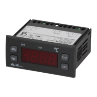
EasyManua.ls Logo

Eliwell IC 912 LX Pt100 R - User Manual

Eliwell IC 912 LX Pt100 R
8 pages
To Next Page IconTo Next Page
Loading...
USER INTERFACE
The user has a display and four keys for
controlling status and programming of the
instrument.
DISPLAY
KEYS AND MENUS
At start-up the instrument performs a
Lamp Test; for five (5) seconds the display
and the leds blink, in order to verify their
integrity and correct operation; afterwards
it will appear the label “Lod” (Loading) for
ten (10) seconds. The instrument has two
main menus: the “Machine Status” and
“Programming” menu.
ACCESSING AND USING MENUS
The resources are arranged in a menu that
can be accessed by pressing and quickly
releasing the “set” button (Machine Status
menu) or holding down the “set” button
for more than 5 seconds (Programming
menu).
To access the contents of each folder indi-
cated by the relevant label, just press the
“set” button once.
You can now scroll through the contents
of each folder, modify it or use its func-
tions. If you do not use the keyboard for
over 15 seconds (time-out) or if you press
the “fnc” button once, the last value
shown on the display is confirmed and
you are taken back to the previous screen
MACHINE STATUS MENU
(See Machine Status Menu Diagram)
To access the Machine Status menu, press
the “set” button and quickly release it.
The “SP1” label appears.
(If alarms are active, with the exception of
faulty probes/probe errors, the “AL” label
appears).
By using the “UP” and “DOWN” buttons
you can scroll through the other folders in
the menu: the folders are indicated below
in the order they appear:
-SP1: Set point 1 setting folder or
-AL: alarm folder (if alarms present, with
exception of faulty probes/probe errors);
-Pb1: probe 1 value folder;
IC 912 LX Pt100°R
electronic controller with single output
and regulation in Réaumur degrees
set
f nc
IC912LX
out
cod. 9IS23094
rel. 11/04
GB
AL
SP1
set
alarms
SP1 value
set
set
t
change
SP1 value
show alarms
press and release
(single press)
if alarm(s)
present
MACHINE STATUS MENU DIAGRAM
Scrolls through the menu items UP button
Increases the values
Parameter programmable
(par. H31)
DOWN button
Scrolls through the menu items
Decreases the values
Parameter programmable
(par. H32)
fnc button ESC function (quit)
Parameter programmable
(par. H33)
Set point button 1-Accesses Machine Status Menu
(SET POINTS, ACTIVE ALARMS,
PROBE READING) and labels/values;
1-Accesses Programming Menu
(PARAMETERS, COPY C ARD) and
relative labels/values;
3-Confirms commands
4-Activates the functions*
fnc
set
Alarm
•ON for active alarm;
•blinking when a silenced alarm is
still present
out1
Relay 1 (OUT1)
• ON for relay on (energized);
•blinking for protection delay or
enabling blocked
Soft Start / Setpoint
ON when Set point is being set
blinking when
Soft Start function is on
Set-point/ Reduced set point
•ON to modify Set-Point;
•blinking when reduced set point
is entered
LED
out1
Question and Answer IconNeed help?

Do you have a question about the Eliwell IC 912 LX Pt100 R and is the answer not in the manual?

Eliwell IC 912 LX Pt100 R Specifications

General IconGeneral
TypeTemperature Controller
InputPt100
Resolution1°C
Frontal ProtectionIP65
Control TypeON/OFF
Display3 digits
OutputRelay
Operating Temperature0 to 50°C
Relay Outputs1 SPDT
Accuracy±0.5% of the scale
Dimensions74x32x60 mm

Summary

User Interface Overview

Machine Status Menu Access

Guide on how to enter and navigate the Machine Status Menu.

Setting and Monitoring Operations

How to Set the Set Point

Instructions for adjusting the desired temperature setpoint value.

Soft Start Functionality

Details on the Soft Start function for gradual temperature ramp-up.

Programming Menu Navigation

Level 1 Parameter Access

Procedure to access and view level 1 parameters in the programming menu.

Level 2 Parameter Access

Procedure to access and view level 2 parameters, potentially requiring a password.

Installation and Technical Specifications

Electrical Wiring Procedures

Safety precautions and instructions for connecting electrical components.

Technical Data Summary

Key specifications including dimensions, temperature ranges, and accuracy.

Usage Conditions and Safety

Permitted use, manufacturer responsibility, and disclaimer information.

Configuration and Function Management

Copy Card Operations

Procedures for uploading and downloading parameter maps using the copy card.

Diagnostics and Troubleshooting

Alarm and Fault Code Interpretation

Guidance on interpreting alarm codes, faulty probe indicators, and error messages.

Related product manuals