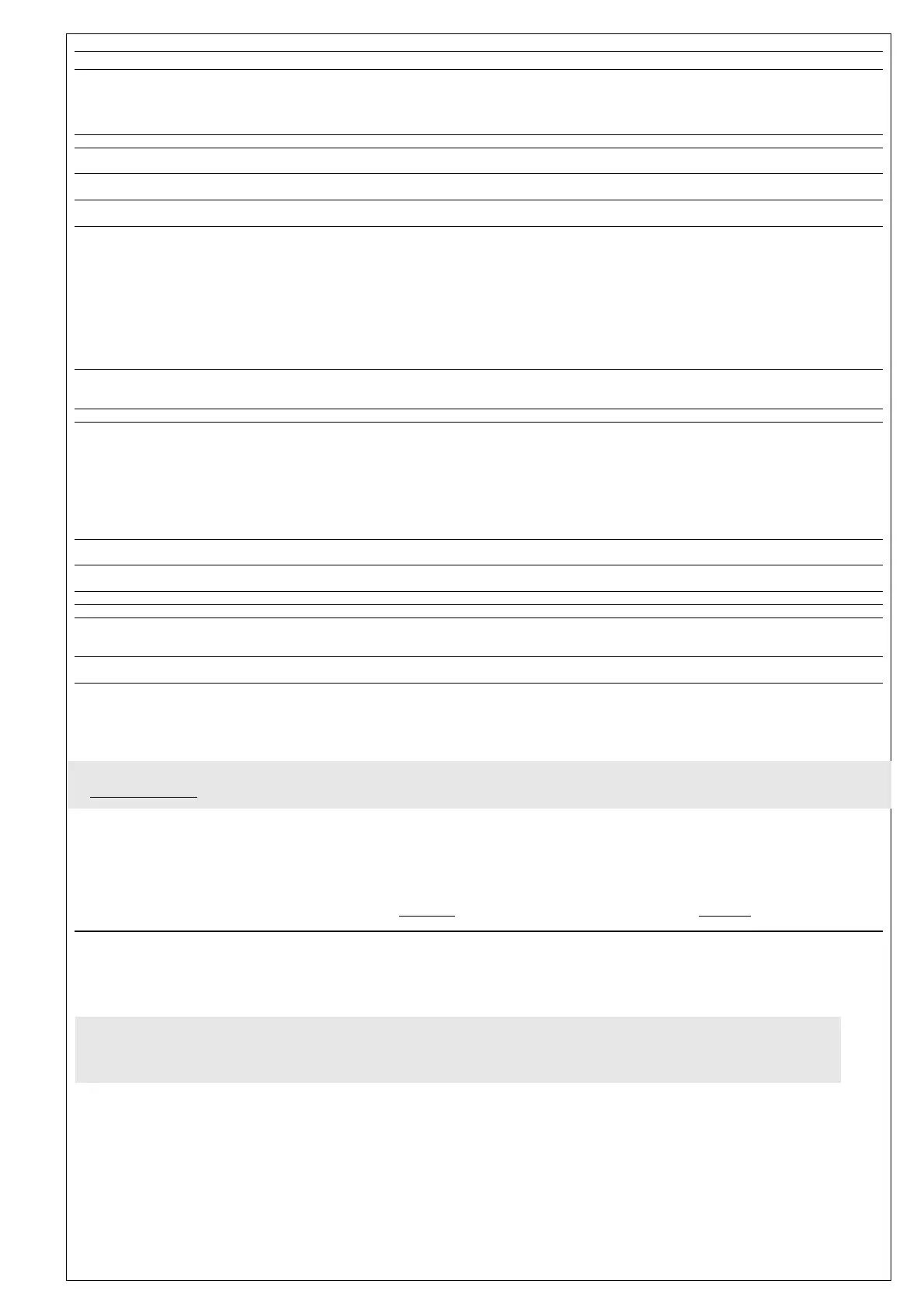
PAR.
H02
H05
H06
H08
H10
H11
H13
H14
H31 (!)
H32 (!)
H33 (!)
rEL
tAb
UL
dL
Fr
(1) Positive values: active input when the contact is closed; negative values: 1= Active when contact is open
(8) Referred exclusively to high and low temperature alarms
* DEFAULT column: for parameters highlighted with * default value depending on model.
** VALUE column: to be filled manually, with custom settings (if different from the default value).
*** LEVEL column: indicates the level of visibility for parameter that can be accessed by a PASSWORD (see the related paragraph)
**** PA2 is visible (it will be requested, if specified) at level 1 in CnF folder
and can be set (it can be modified) at level 2 in diS folder
(!) WARNING!
• If one or more of these parameters highlighted with (!) are modified, the controlller must be switched off and switched on again to ensure correct operation.
• It is strongly recommended, anyway to switch off and switch on again the controller anytime parameters have been changed to prevent malfunctioning on configuration
and/or ongoing timings
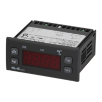
IC 912 LX Pt100 °R 6/8
DESCRIPTION
CONFIGURATION (folder with “CnF” label)
Time to enable keys, if these are configured for a specific func-
tion. For ESC, UP and DOWN keys configured for specific function
(defrost, aux, etc) it set the elapsed time for the manual activa-
tion of the related function. aux function has a fixed time of 1
second
Window Filter. -2=very fast; -1=fast; 0=normal; =slow; 2=very slow
key/input aux/door switch light active when instrument is off (but
under tension)
Stand-by operating mode. 0=display switch off; 1= diplay on and
loads stopped; 21= display off and loads stopped;
Delay outputs from power-on. WARNING! If set = 0 it is not
active; if set ≠0 output will not be activated before this time
Configuring digital inputs.
0 = disabled;
1 = SOFT START;
2 = Offset Setpoint;
3 = outputs stopped;
4 = not used;
5 = auxiliary output;
6 = stand-by
7 = maintenance requested
8 = external alarm
9 = external alarm stop regulators
Polarity and Priority Digital Input
no= normally open/ nc= normally closed / noP= normally open
with Polarity / ncP= normally close with Polarity
Delay Activation Digital Input
Configurability UP key.
0 = disabled;
1 = SOFT START;
2 = Offset Setpoint;
3 = outputs stopped;
4 = not used;
5 = auxiliary output;
6 = stand-by
7 = maintenance requested
Configurability DOWN key.
Same as H31.
Configurability ESC key.
Same as H31. ( 2 = Offset Setpoint; default)
reLease firmware. Device version: read only parameter.
tAble of parameters. Reserved: read only parameter.
COPY CARD (folder with “Fpr”label)
Up load. Programming parameter transfer from instrument to
Copy Card.
Down load. Programming parameter transfer from Copy Card to
instrument
Format. Erasing all data in the copy card.
PLEASE NOTE using “Fr” parameter (copy card formatting)
the data within the copy card will be lost permenently. The
operation cannot be cancelled. After using the copy Card
device the controller must be switch off and switch on again
DEFAULT*
5
0
y
2
0
0
no
0
0
0
0
/
/
/
/
/
RANGE
0…15
-2/+1/0/1/2
n/y
0/1/2
0...250
0…9
no/nc/noP/ncP
0…250
0…7
0…7
0…7
/
/
/
/
/
VALUE**
U.M.
sec
°R
flag
num
min
num
num
num
num
num
num
/
/
/
/
/
LEVEL**
2
2
2
2
1
2
2
2
2
2
2
1
1
1
1
1
label PA2
Inside CnF folder it is possible to reach all level 2 parameters from label PA2 by pressing the “set” button
SEE 2) level 2 P
arameters paragraph
FUNCTIONS (folder with label “FnC”)
Inside FnC folder (last visble folder from Programming Menu) there are available some functions that could be enabled by “set” button
SEE FUNCTIONS paragraph

 Loading...