EasyManua.ls Logo

Eliwell EWPlus 974 User Manual

Eliwell EWPlus 974
8 pages
To Next Page IconTo Next Page
Page #1 background imageLoading...
Page #1 background image
Reduced SET / Economy LED
Permanently on: Energy Saving active
Flashing: Reduced SET active
Quick flashing: access to level2 parameters
Off: otherwise
Fans LED
Permanently on: fans active
Off: otherwise
Compressor LED
Permanently on: compressor active
Flashing: a delay, a protection or a
locked start-up
Off: otherwise
Aux LED
Permanently on: Aux output active
Flashing: Deep Cooling cycle active
Off: Aux output not active
Defrost LED
Permanently on: defrost active
Flashing: manual or D.I. activation
Off: otherwise
HEAT mode LED
Permanently on: compressor in HEAT mode
Off: otherwise
(only EWPlus 961)
°C LED
Permanently on: °C setting (dro = 0)
Off: otherwise
NOTE:
If the instrument is set in the COOL mode, in order to use
it in the HEAT mode it is necessary to reprogramme the
instrument by using the properly programmed Copycard.
The same procedure should be followed to pass from the
HEAT mode to the COOL mode.
°F LED
Permanently on: °F setting (dro = 1)
Off: otherwise
Alarm LED
Permanently on: alarm active
Flashing: alarm acknowledged
Off: otherwise
NOT USED
(only EWPlus 961)
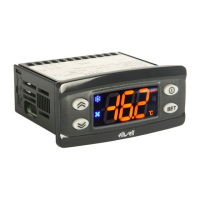
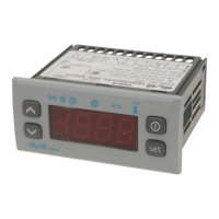
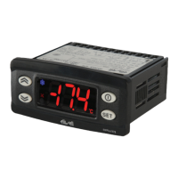
EWPlus 961/971/974
Electronic controllers for refrigeration units
NOTE:
When switched on, the device performs a Lamp Test; the
display and LEDs will flash for several seconds to check that
they all function correctly.
USER INTERFACE
UP
Press and release
Scroll menu items
Increases values
Press for at least 5 sec
Activates the Manual Defrost function
DOWN
Press and release
Scroll menu items
Decrease values
Press for at least 5 sec
Function can be configured by the user
((see parameter H32)
STAND-BY (ESC)
Press and release
Returns to the previous menu level
Confirms parameter value
Press for at least 5 sec
Attiva la funzione Stand-by (OFF)
(quando non sono all’interno dei menu)
SET (ENTER)
Press and release
Displays alarms (if active)
Opens Machine Status menu
Press for at least 5 sec
Opens Programming menu
Confirm commands
KEYs
EN
MOUNTING - DIMENSIONS
The device is designed for panel mounting. Drill a 29x71 mm hole and insert the instrument; secure it with the special brackets
provided. Do not install the instrument in damp and/or dirty places; in fact, it is suitable for use in places with ordinary or normal levels
of pollution. Keep the area around the instrument cooling slots adequately ventilated.
74 mm
32 mm
29 mm
71 mm
70 mm
59 mm

Other manuals for Eliwell EWPlus 974

Question and Answer IconNeed help?

Do you have a question about the Eliwell EWPlus 974 and is the answer not in the manual?

Eliwell EWPlus 974 Specifications

General IconGeneral
Resolution0.1°C
Front panel protectionIP65
Power consumption3VA max
Output typeRelay
Operating temperature-5°C to 55°C
Storage temperature-20°C to +70°C
Measuring range-50°C to +150°C (depending on sensor)
Accuracy±0.5°C
Serial communicationTTL for external module
Output rating8A/250V AC (resistive load)
Relative humidity20% to 90% (non-condensing)
Protection degreeIP20 (housing), IP65 (front panel)
Dimensions74 x 32 x 60 mm
Relay outputs3 relays: Relay 1: 8(3)A 250Vac; Relay 2: 8(3)A 250Vac; Relay 3: 8(3)A 250Vac

Summary

User Interface Overview

User Interface LEDs

Explains the function of various LEDs like Reduced SET, Compressor, Defrost, Alarm, Fans, AUX, and HEAT mode.

Mounting and Dimensions

Installation Guidelines

Details panel mounting requirements, hole dimensions, and ventilation needs for optimal operation.

Electrical Connections

EWPlus 961 Terminals

Specifies terminal assignments for compressor, power supply, probe, and digital input.

EWPlus 971 Terminals

Details terminal connections for compressor, defrost, probes, and digital input.

EWPlus 974 Terminals

Lists terminal connections for fans, compressor, defrost, probes, and digital input.

ECPlus Integration

ECPlus and EWPlus Connection

Illustrates the connection method between ECPlus and EWPlus units via TTL serial port.

Menu Navigation and Usage

Programming Menu Access

Entry into the parameter configuration menu, requiring passwords PA1 or PA2.

Unicard/Copycard Usage

Instructions for uploading and formatting parameters using the Copy Card.

Diagnostics and Alarms

Defrost and Temperature Alarms

Alarms related to defrost timeout (Ad2) and temperature limits (HAL, LAL).

Technical Specifications

Electrical Connection Precautions

Safety and Wiring Guidelines

Ensures safe electrical connections by following power-off, wire gauge, and cable routing rules.

Related product manuals