Do you have a question about the Eliwell EWPlus 971 and is the answer not in the manual?
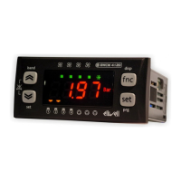
Details the function and status of various LEDs including Compressor, Defrost, Alarm, and Fan indicators, and operational modes.
Describes the primary and long-press functions of the UP, DOWN, STAND-BY (ESC), and SET (ENTER) keys.
Provides instructions for panel mounting, securing the instrument, and ensuring adequate ventilation around cooling slots.
Details the terminal connections for the EWPlus 961 model, including compressor relay, power supply, and probe inputs.
Details the terminal connections for the EWPlus 971 model, including defrost and compressor relays, and probes.
Details the terminal connections for the EWPlus 974 model, including fan, defrost, and compressor relays, and probes.
Illustrates the connection between ECPlus and EWPlus units, specifying a maximum cable length of 5m.
Explains how to enable and manage PA1 for User parameters and PA2 for Installer parameters, including default values and access methods.
Details how to access the Machine Status menu to view alarms, setpoints, and probe data.
Explains how to access the Programming menu for User and Installer parameters, including navigation and modification.
Describes how to lock or unlock the keypad to prevent unauthorized changes to the setpoint value.
Explains how to upload, download, and format parameters using the Unicard/Copycard for rapid instrument programming.
Details the procedure to manually activate the defrost cycle by holding a key for 5 seconds, including conditions for operation.
Lists common alarm fault codes (E1, E2, AH1, AL1, EA, OPd, Ad2) with their causes, effects, and recommended remedies.
Explains how maximum and minimum temperature alarms are triggered based on setpoints and differentials, with relative and absolute temperature values.
Details input/output characteristics, mechanical features like casing, terminals, and regulatory compliance.
Provides further details on probe specifications, measurement accuracy, and notes on technical specifications referring to the instrument.
Emphasizes safety precautions before making electrical connections, including wire diameter, current limits, voltage compliance, and probe cable routing.
Details installer parameters related to compressor operation (e.g., differentials, delays, fault times) and defrost cycle settings.
Details installer parameters for fan control (e.g., operating modes, exclusion during defrost) and alarm settings (e.g., temperature differentials).
Covers keypad locking, password access, temperature units, decimal display, and defrost display modes.
Details configuration for stand-by modes, digital inputs/outputs, the DOWN key function, and evaporator probe presence.
Describes the UL function to upload parameters to the Copy Card and the Fr function to format the card, erasing all data.
States Eliwell's disclaimer of liability for damages arising from improper installation, use, or tampering with the product.
Asserts the document's exclusive property and limits Eliwell's liability for damages resulting from its use or editing.
Outlines the permitted uses of the instrument, emphasizing safety, and prohibits any other usage, especially concerning relay contacts.
| Model | EWPlus 971 |
|---|---|
| Front Protection | IP65 |
| Type | Controller |
| Input Type | NTC, PTC |
| Display | LCD |
| Power Supply | 230V AC |
| Relay Output | SPDT 250 V AC |
| Communication | RS485 |
| Operating Temperature | -10°C to +55°C |
| Storage Temperature | -20°C to +70°C |
| Measuring Range | -50 to +150 °C |
| Accuracy | ±0.5% f.s. ±1 digit |
| Resolution | 0.1 °C |
| Digital Inputs | 2 |
| Protection Degree | IP65 |
| Dimensions | 96 x 96 mm |
| Weight | 300 g |