EWPlus + ECPlus
6/8
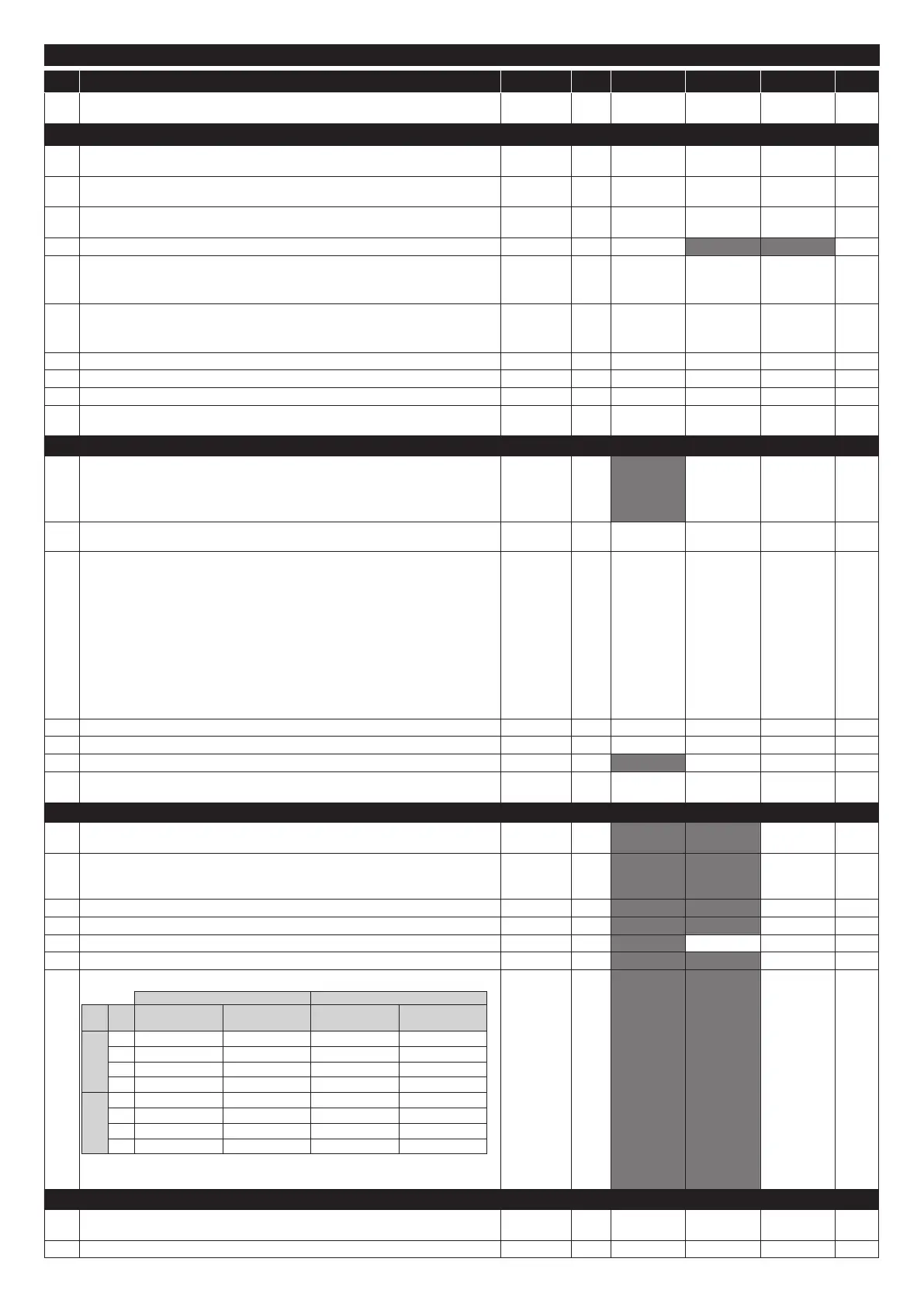
PAR. DESCRIPTION RANGE M.U. EWPlus 961 EWPlus 971 EWPlus 974 LEVEL
SEt
Temperature control SEtpoint.
The SEtpoint is visible from the "machine status" menu only.
LSE ... HSE °C/°F 0.0 0.0 0.0
COMPRESSOR ('CP' folder)
dF1
diFferential. Compressor relay activation differential.
N.B.: diF cannot be equal to 0.
0.1 ... 30.0 °C/°F 2.0 2.0 2.0 1&2
HSE
Maximum value that can be assigned to the Setpoint. N.B.: The two Setpoints are
interdependent: HSE cannot be less than LSE and vice-versa.
LSE ... 320 °C/°F 99.0 99.0 99.0 1&2
LSE
Minimum value that can be assigned to the Setpoint. N.B.: The two Setpoints are
interdependent: LSE cannot be higher than HSE and vice-versa.
-67.0 ... HSE °C/°F -50.0 -50.0 -50.0 1&2
HC The regulator will go to HOT operating mode (‘H’) or COLD operating mode (‘C’) C/F flag C 2
Ont
Controller ON time for faulty probe.
- if Ont = 1 and OFt = 0, the compressor remains ON
- if Ont > 0 and OFt > 0, it runs in duty cycle mode.
0 ... 250 min 0 0 0 2
OFt
Controller OFF time for faulty probe.
- if OFt = 1 and Ont = 0, the compressor remains OFF
- if Ont > 0 and OFt > 0, it runs in duty cycle mode.
0 ... 250 min 1 1 1 2
dOn Compressor relay activation delay after request. 0 ... 250 secs 0 0 0 2
dOF Delay after switching off and subsequent activation. 0 ... 250 min 0 0 0 2
dbi Delay between two consecutive compressor activations. 0 ... 250 min 0 0 0 2
OdO
(!)
Delay in activating outputs after the instrument is switched on or after a power failure.
0 = not active.
0 ... 250 min 0 0 0 2
DEFROST ('dEF' folder)
dty
Type of defrost.
0= electric defrost - compressor OFF during defrost cycle
1= cycle inversion defrost (hot gas) - compressor ON during defrost cycle
2= ‘Free’: defrosting independently of compressor
0/1/2 num 0 0 1&2
dit
Interval between the start of two consecutive defrost cycles.
0 = function disabled (defrosting NEVER performed)
0 ... 250 hours 6 6 6 1&2
dCt
Selects the count mode for the defrost interval:
0 = compressor hours of operation (DIGIFROST® method);
Defrost active ONLY when the compressor is on.
NOTE: compressor operation time is counted separately from the evaporator
probe (count active also when evaporator probe missing or faulty).
1 = appliance running hours = the defrost count is always active when the machine is on
and starts at each power-on;
2 = compressor stop Every time the compressor stops, a defrost cycle is performed
according to parameter dtY;
3 = temperature.
0/1/2/3 num 1 1 1 2
dOH Defrost start delay time after request. 0 ... 59 min 0 0 0 2
dEt Defrost time-out; determines the maximum defrost duration. 1 ... 250 min 30 30 30 1&2
dS1 Defrost end temperature (determined by the evaporator probe). -67.0 ... 320 °C/°F 8.0 8.0 1&2
dPO
Determines whether the instrument must enter defrost mode (if the temperature
measured by the evaporator allows this operation). n = no; y = yes.
n/y flag n n n 2
FANS ('FAn' folder)
FPt
Characterizes the "FSt" parameter that can be expressed or as an absolute temperature
value or as a value related to Setpoint. 0 = absolute; 1 = relative.
0/1 flag 0 2
FSt
Fan lock temperature; if Pb2 > FSt, the fans are stopped.
The value is either positive or negative and, depending on parameter FPt, can
be either the absolute temperature or the temperature relative to the Setpoint.
-67.0 ... 320 °C/°F 50.0 1&2
FAd Fan starting differential (see parameter FSt). 1.0 ... 50.0 °C/°F 2.0 2
Fdt Delay time in activating fans after a defrost operation. 0 ... 250 min 0 1&2
dt drainage time. Dripping time. 0 ... 250 min 0 0 1&2
dFd Allows to select the evaporator fans exclusion during defrost. y = yes; n = no. n/y flag y 1&2
FCO
Evaporator fans operating mode. The state of the fans will be:
DAY NIGHT
H42 FCO
COMPRESSOR
ON
COMPRESSOR
OFF
COMPRESSOR
ON
COMPRESSOR
OFF
H42 = y
0 Regulated by Pb2 OFF Regulated by Pb2 OFF
1 Regulated by Pb2 Regulated by Pb2 Regulated by Pb2 Regulated by Pb2
2 Regulated by Pb2 Dutycycle Day Regulated by Pb2 Dutycycle Night
3 Dutycycle Day Dutycycle Day Dutycycle Night Dutycycle Night
H42 = n
0 ON OFF ON OFF
1 ON Dutycycle Day ON Dutycycle Night
2 ON Dutycycle Day ON Dutycycle Night
3 Dutycycle Day Dutycycle Day Dutycycle Night Dutycycle Night
Dutycycle Day: controlled by means of parameters “Fon” and “FoF”.
Dutycycle Night: controlled by means of parameters “Fnn” and “FnF”.
0/1/2/3 num 1 2
ALARMS ('AL' folder)
Att
Parameters HAL and LAL intended as the absolute temperature value or differential in
relation to the setpoint. 0 = absolute value; 1 = relative value.
0/1 num 1 1 1 2
AFd Alarm differential. 1.0 ... 50.0 °C/°F 2.0 2.0 2.0 2
TABLE OF "INSTALLER" MENU PARAMETERS

 Loading...