EWPlus + ECPlus
4/8
ALARMs
Label Fault Cause Effects Remedy
E1
Probe1 faulty
(cold room)
• measured values are outside operating
range
• Probe faulty / short-circuited / open
• Display label E1
• Alarm icon permanently on
• Disable max/min alarm controller
• Compressor operation based on parameters
“Ont” and “OFt”.
• check probe type (NTC)
• check probe wiring
• replace probe
E2
Probe2 faulty
(defrost)
only on
EWPlus 971/974
• measured values are outside operating
range
• Probe faulty / short-circuited / open
• Display label E2
• Alarm icon permanently on
• The Defrost cycle will end due to Timeout (dEt)
• The evaporator fans will work in Duty Cycle
mode.
• check probe type (NTC)
• check probe wiring
• replace probe
AH1
Alarm for HIGH
Pb1 temperature
value read by Pb1 > HAL after time of tAO.
(see “MAX/MIN TEMPERATURE ALARMs")
• Recording of label AH1 in folder AL
• No effect on regulation
• Wait until value read by Pb1 returns below
HAL-AFd.
AL1
Alarm for LOW
Pb1 temperature
value read by Pb1 < LAL after time of tAO.
(see “MAX/MIN TEMPERATURE ALARMs")
• Recording of label AL1 in folder AL
• No effect on regulation
• Wait until value read by Pb1 returns above
LAL+AFd.
EA External alarm
digital input activation
(H11 = ±5)
• Recording of label EA in folder AL
• Alarm icon permanently on
• Regulation locked if rLO = y
• check and remove the external cause which
triggered the alarm on the D.I.
OPd Door open alarm
digital input activation
(H11 = ±4)
(for longer than tdO)
• Recording of label Opd in folder AL
• Alarm icon permanently on
• Controller locked
• close the door
• delay function defined by OAO
Ad2
end of defrost
cycle due to timeout
end of defrost cycle due to timeout rather
than due to defrost end temperature being
recorded by probe Pb2.
• Recording of label Ad2 in folder AL
• Alarm icon permanently on
• wait for the next defrost cycle for automatic
return
DIAGNOSTICS
Alarms are always indicated by the buzzer (if present) and the alarm icon .
To switch off the buzzer, press and release any key; the corresponding icon will continue to flash.
NOTE: If alarm exclusion times have been set (see “AL” folder in the parameters table) the alarm will not be signalled.
- E1: in the event of cold room probe faulty (Pb1), the indication “E1” will appear on the display.
- E2: in the event of defrost probe faulty (Pb2), the indication “E2” will appear on the display (EWPlus 971/974 models only).
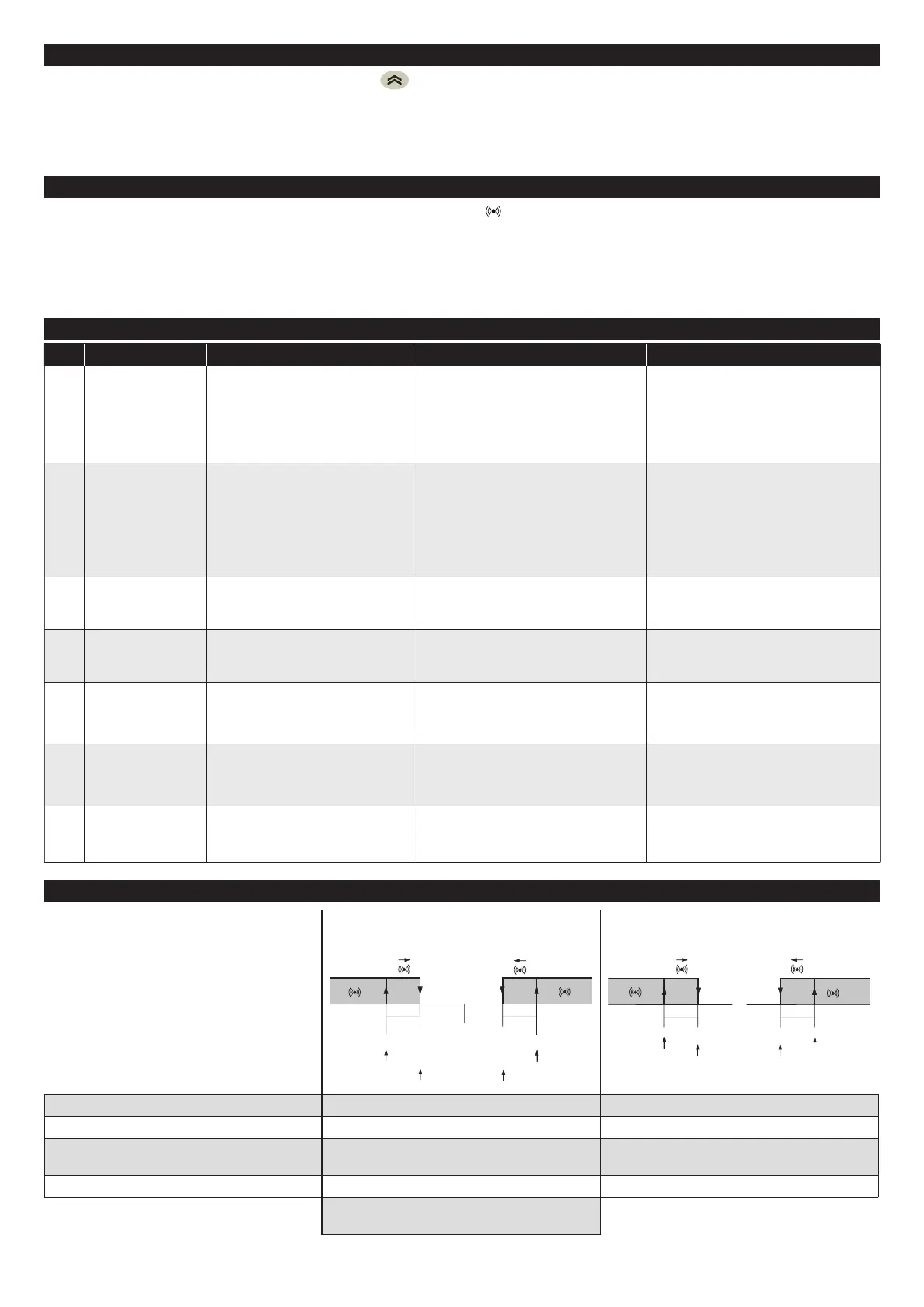
Relative Temperature
Value to setpoint (Att=1)
Absolute Temperature
Value (Att=0)
SEt + LAL
AFd
SEt + HAL
AFd
SEt + LAL + AFd
SEt + HAL – AFd
SEt
LAL
AFd
HAL
AFd
LAL + AFd
LAL - AFd
Minimum temperature alarm Temp. ≤ Set + LAL * Temp. ≤ LAL (LAL with sign)
Maximum temperature alarm Temp. ≥ Set + HAL ** Temp. ≥ HAL (HAL with sign)
Returning from minimum temperature alarm
Temp. ≥ Set + LAL + AFd or
≥ Set - ILALI + AFd (LAL < 0)
Temp. ≥ LAL + AFd
Returning from maximum temperature alarm Temp. ≤ Set + HAL - AFd (HAL > 0) Temp. ≤ HAL - AFd
* if LAL is negative, Set + LAL < Set
** if HAL is negative, Set + HAL < Set
MAX/MIN TEMPERATURE ALARMs
MANUAL DEFROST CYCLE ACTIVATION
To manually activate the defrost cycle, hold down the key for 5 seconds.
If the defrost conditions are not satisfied:
- parameter OdO ≠ 0 (EWPlus 961/971/974)
- probe Pb2 temperature is higher than the defrost end temperature (EWPlus 971/974)
the display will flash 3 times, to indicate that the operation will not be carried out.