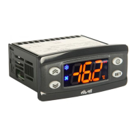
USER INTERFACE
The user has a display and four buttons
for controlling instrument status and pro-
gramming. The device can also be con-
nected to a remote display.
At start-up the instrument performs a
Lamp Test; the display and LEDs flash for a
few seconds to check that they are work-
ing correctly. The instrument has two main
menus: the Machine Status menu and the
Programming menu.
ACCESSING AND USING MENUS
The resources are arranged in a menu that
can be accessed by pressing and quickly
releasing the “set” button (Machine Status
menu) or holding down the “set” button
for more than 5 seconds (Programming
menu). To access the contents of each
folder indicated by the relevant label, just
press the “set” button once.
You can now scroll through the contents
of each folder, modify it or use its func-
tions.
If you do not use the keyboard for over 15
seconds (time-out) or if you press the
“fnc” button once, the last value shown on
the display is confirmed and you are taken
back to the previous screen mask.
REMOTE DISPLAY
This has a display with 3 digits + sign that
displays the parameter programming and
alarm display values on the controller it is
connected to during probe reading.
MACHINE STATUS MENU
(See Machine Status Menu Diagram)
Position Associated function Status
Set point/Reduced set point ON for parameter programming level 2
blinking when reduced set point is entered
(set point ON for setting set point)
Compressor or relay 1 ON for compressor on; blinking
for protection delay or enabling blocked
Defrosting ON when defrosting in progress; blinking when activated
manually or by digital input
Alarm ON for active alarm; blinking for silenced alarm
Fans ON when fan is on
aux ON when auxiliary output is operating
UP button
Scrolls through the menu items
Increases values
Activates manual defrosting
(see H31 parameter)
DOWN button
Scrolls through the menu items
Decreases the values
Parameter programmable
(see H32 parameter)
fnc button
ESC function (quit)
Parameter programmable
(see H33 parameter
Set button
Accesses Set point and rtc folder
Accesses the Menus
Confirms the commands
Displays the alarms (if active)
Stores hours/min
cod. 9IS23080
rel. 4/08 -GB-
ID 985/S/E/CK - ID985/E LX
electronic controllers for “ventilated” refrigeration units
ww
ww
ii
ii
tt
tt
hh
hh
RR
RR
SS
SS
44
44
88
88
55
55
oo
oo
nn
nn
bb
bb
oo
oo
aa
aa
rr
rr
dd
dd
((
((
II
II
DD
DD
99
99
88
88
55
55
//
//
SS
SS
//
//
EE
EE
//
//
CC
CC
KK
KK
))
))
aa
aa
nn
nn
dd
dd
rr
rr
ee
ee
mm
mm
oo
oo
tt
tt
ee
ee
dd
dd
ii
ii
ss
ss
pp
pp
ll
ll
aa
aa
yy
yy
BUTTONS AND DISPLAY