The device consists of two units:
• a IWK keyboard available in 3 sizes
(see below and in paragraph on
Models)*;
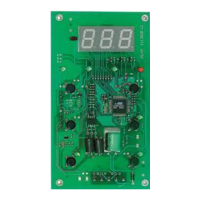
• an IWP power module.
The IWK keyboard is connected to the
IWP power module using an “powered”
serial connection also referred to as
SHORT DISTANCE.
*Different types of IWK keyboards are
available: the functions and connec-
tion of the standard 32x74 4 button
IWK keyboard are illustrated below.
For information on this and other key-
boards, refer to the relevant technical
data sheets.
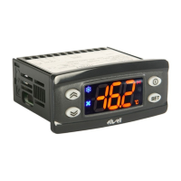
USER INTERFACE
(example of a standard 32x74 4-button
keyboard).
The user has a keyboard with a 6 LED
display and four buttons for controlling
status and programming of the instru-
ment.
BUTTONS AND MENUS
UP Button
Scrolls through the menu items
Increases the values
Parameter programmable*
(see H31 parameter: by default
Manual DEFROST is defrost)
DOWN Button
Scrolls through the menu items
Decreases the values
Parameter programmable*
(see parameter H32, by default
aux relay is active)
ESC button
ESC function (exit)
Parameter programmable*
(see H33 parameter)
set button
(press once)
MACHINE STATUS MENU
•Accesses the set point
•Displays the alarms
(if active)
•Dispays Pb1,Pb2 and Pb3
(see)
(hold down)
•Accesses the programming
Menu Parameters
UP button +esc button pressed simultaneously
(press for 2 seconds)
•Keyboard locking/unlocking
FOR WIDE AND 6 BUTTON IWK KEYBOARDS
“secondary” or function buttons
“ON-OFF” (hold down, see par.H02)
(function 2)
Switches unit on/off
Parameter programmable*
(see H35 parameter)
“LIGHT” button (function 1)
Switches on the light
Parameter programmable*
(see H34 parameter)
*NOTE:
The “primary” buttons can be pro-
grammed using the parameters H31…H33
(see)
In standard configuration the buttons are
set by default as:
• “UP” button; par. H31=1; enables
manual defrosting
• “DOWN” button; par. H32=0 no related
function (disabled)
• “esc” button; par. H33=3 enables the
reduced set function
• “set” button; not programmable.
LEDS
“Display” LEDs
The display is red, the 6 LEDs are red
“eco” LED
•ON for parameter programming level 2;
•blinking when OSP reduced set is entered
Compressor LED
ON for compressor on;
•blinking for protection delay, or enabling
blocked.
Defrosting LED
ON when automatic defrosting in progress;
•blinking when manual defrosting is in
progress;
LED Fans
•ON when fan is on;
•blinking for manual or D.I. (Digital Input)
fan forcing
(%RH function, humidity reduction
if par. H11=13)
Alarms LED
•ON for active alarm;
•blinking for silenced alarm
FOR IWK WIDE AND 6-BUTTON LED
KEYBOARDS ONLY
“set” LED
•ON for paramter programming level 2;
•blinking when OSPreduced set is entered
“on-off” LED
ON when unit “off” (on STAND-BY);
•OFF when unit on;
“light” LED
ON when output is active, (%RH / light
depending on model and/or default set-
tings);
ON when output is also active from D.I.
IWP 740 (LX)
Electronic controllers for “ventilated” refrigerating units
Model
IWK keyboard
IWK std 6 buttons
IWK 32x74 4
buttons
IWK wide
6 (max 8) buttons
IWP power module
IWP 740 (LX)
Characteristics
open board keyboard
68x124mm (LxH)
Eliwell std. keyboard
32x74x60mm (LxHxD)
“IWC” style keyboard
180x37x45mm (LxHxD)
base module with 4 relays
92x121mm (LxH)
MODELS