I GB
(((ELKRON)))
MS04/MS04PK14
14.0 CARATTERISTICHE FUNZIONALI
14.1 CONTROLLO ALIMENTAZIONE
• Il microfono è predisposto per funzionare in un
RANGE compreso tra i 9 Vdc ed i 15 Vdc. Al di fuori
da tali valori il microfono blocca automaticamente il
suo funzionamento con conseguente apertura del
contatto di allarme. Al rientro della tensione di ali-
mentazione (ai valori compresi nel range) il microfo-
no esegue automaticamente la procedura descritta
nella PRIMA ALIMENTAZIONE.
14.2 AUTOTEST
• Ogni 5 minuti il microfono esegue un AUTOTEST
analizzando tutti i circuiti analogici e l’efficienza del
sistema di rilevazione. Una eventuale anomalia de-
termina la commutazione delle uscite di allarme ed il
lampeggio del LED relativo al canale guasto.
14.3 COMANDO REMOTE
• Applicando una tensione 0Vdc sull’ingresso -R il mi-
crofono raddoppia automaticamente il ritardo
(RESPONSE) programmato. In questo modo qualora
fosse posto a protezione di BAMCOMAT è possibile
evitare che si produca un allarme inopportuno a cau-
sa dei disturbi generati dalle operazioni di prelievo
(meccanismo per la stampa) - per tale connessione
occorre estrapolare il segnale dai comandi elettrici del-
l’apparato.
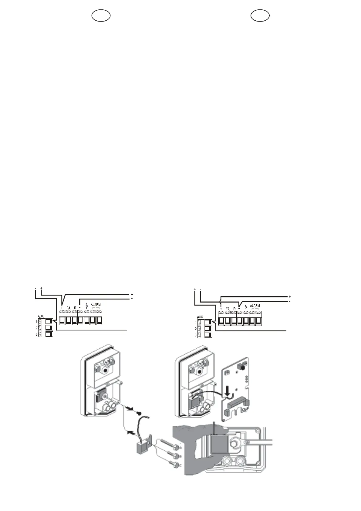
15.0 INST. PERTURBATORE INTERNO
ESEMPIO DI CONNESSIONE CON COMANDO NEGATIVO (-12V)
EXAMPLE OF NEGATIVE CONTROL CONNECTION (-12V)
ALIMENTAZ. MICROFONO
DETECTOR SUPPLY
COMANDO (-12Vdc)
CONTROL (-12Vdc)
PERTURBATORE
PERTURBATOR
ALIMENTAZ. MICROFONO
DETECTOR SUPPLY
COMANDO (+12Vdc)
CONTROL (+12Vdc)
PERTURBATORE
PERTURBATOR
ESEMPIO DI CONNESSIONE CON COMANDO POSITIVO
(+12V)
EXAMPLE OF POSITIVE CONTROL CONNECTION (+12V)
14.0 FUNCTIONAL CHARACTERISTICS
14.1 POWER TEST
• The microphone is set up to work in a RANGE from 9
Vdc to 15 Vdc. Out of this range, the microphone will
automatically stop working and open the alarm con-
tact. When the voltage returns with the specified range,
the microphone will automatically run the procedure
described in FIRST POWER ON.
14.2 SELF-TEST
• The microphone will run a SELF-TEST every five min-
utes, analysing the analogue circuits and the efficiency
of the detection system. Any failures will switch the
alarm outputs and the faulty channel LED will flash.
14.3 REMOTE CONTROL
• The microphone automatically double the programmed
delay (RESPONSE) by applying a voltage of 0Vdc on
the -R input. In this way, when the device is used to
protect an ATM, this prevents generating an inappro-
priate alarm during tilling operations (printing the re-
ceipt). The electrical control signals of the device will
need to be extrapolated for this connection.
15.0 INTERNAL PERTURBATOR
INSTALLATION
A STRUTTURE MURARIE
B STRUTTURE COMPOSITE
C STRUTTURE METALLICHE
A WALL STRUCTURES
B COMPOSITE STRUCTURES
C METALLIC STRUCTURES
 Loading...