Power Supply
General
230v - 50Hz
Working Temp
Max Accessories Load
Protection Fuses
1) Specification and Installation
Max Motor Load
Dimensions (mm)
3.0
Weight (Kg)
Batteries 2 x 12V 1.3Ah
Ext 24v d.c: F1 = T4A, Delayed
Mains: F2 = T200mA, Delayed
Relays: F3 = T6.3A, Delayed
236 (w) x 286 (h) x 108 (h)
6.3A @ 230v
4A @ 24v d.c
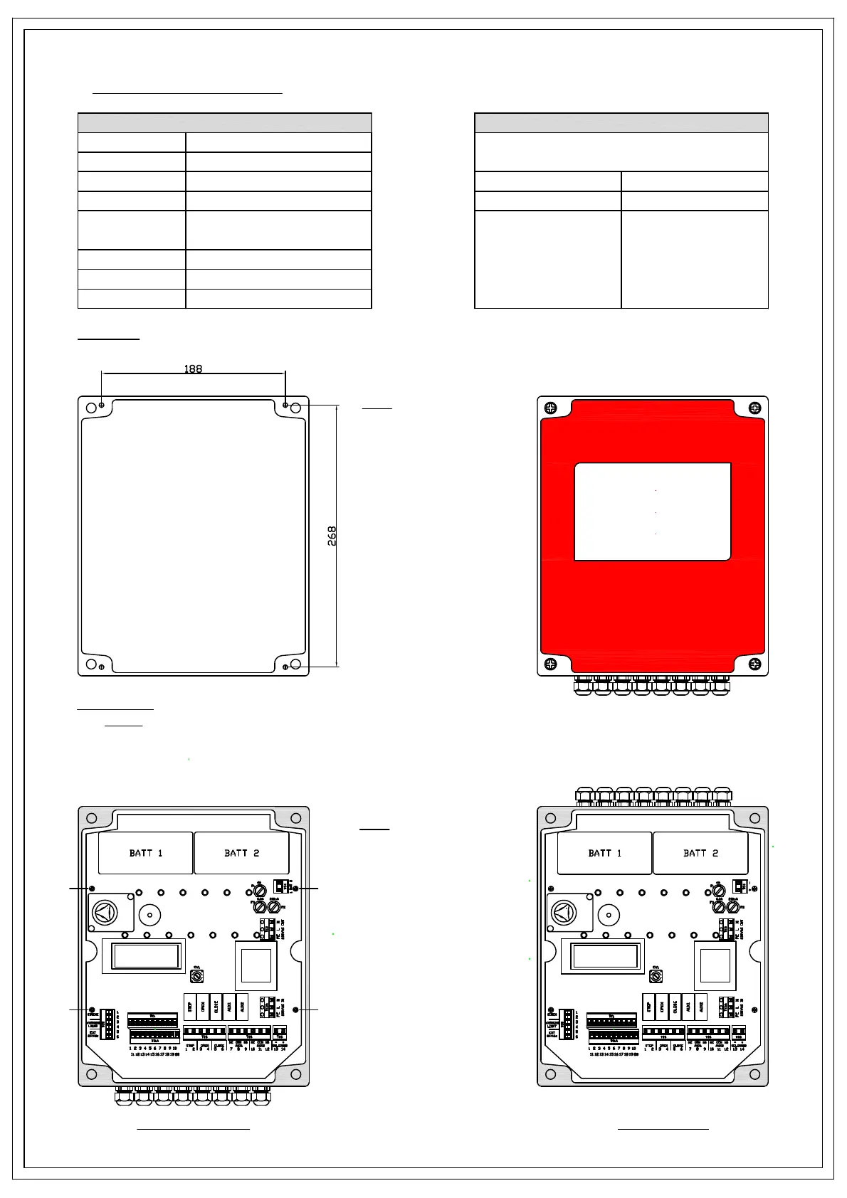
Cable Entry
The FDCP is designed so the cable entry can be positioned at
the top or bottom of the panel by means of removing the PCB
fixing screws, then rotating either board or box 180° and
refitting (see Fig 1.2)
Mounting
Mount the unit using the fixing holes provided (see Fig 1.1)
BOTTOM CABLE ENTRY
+
-
+
-
+
-
+
-
+
-
+
-
'A'
'A'
'A'
'A'
Fig 1.1
Enclosure Mounting
TOP CABLE ENTRY
Fig 1.2
Cable entry positions
Remove fixing screws 'A' and rotate
board or box
WARNING
FIRE
SHUTTER
CLOSING
Standards and Conformity
Directive 2004/108/EC
Directive 2006/95/EC
EMC Directive:
Low Voltage Requirements:
and In association with:
EN 60204-1: 2006+A1: 2009
EN 61000-6-1: 2007
EN 61000-6-2: 2005
EN 61000-6-3: 2007+A1: 2011
EN 61000-6-4: 2007+A1: 2011
EN 12453:2001
EN 50272-2: 2001
The FDCP complies to the following EMC and Low Voltage
standards and directives
-20 to +70°C