page 6
6. Wiring. (cont.)
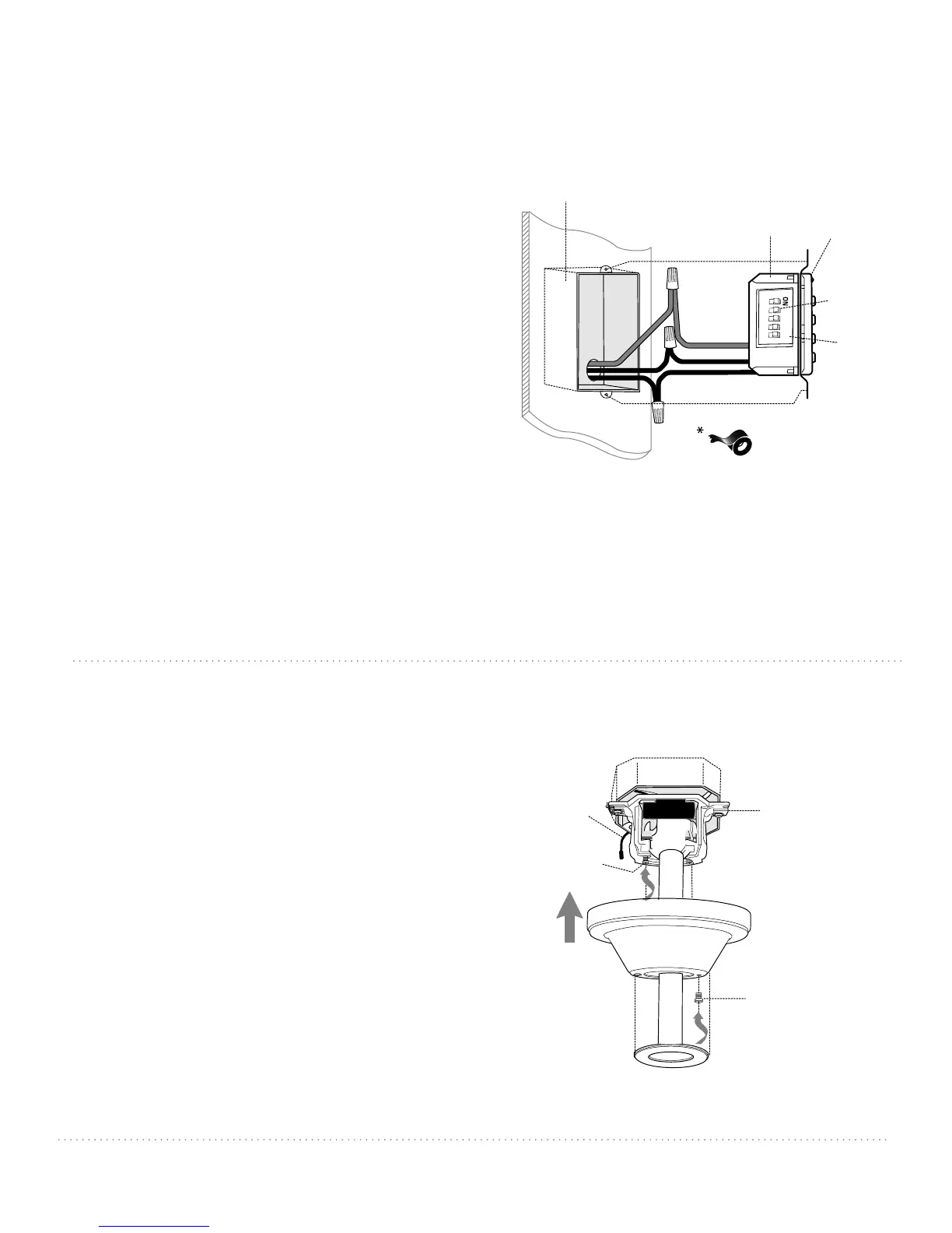
7. Canopy Assembly.
Locate 2 screws on underside of hanging bracket and
remove screw closest to the open end of the hanging
bracket. Partially loosen the other screw. Lift canopy to
hanging bracket. Place rounded part of slotted hole in
canopy over loosened screw in hanging bracket and
push up. Twist canopy to lock. Re-insert screw that was
removed and then tighten both screws securely. Slide
canopy cover up to canopy, aligning rounded part of
slotted holes in canopy cover with screwheads in
bottom of canopy. Turn canopy cover to the right
(clockwise) until it stops.
*Remember that antenna for remote control receiver
must rest outside of hanging bracket.
canopy cover
screw
canopy
hanging bracket
screw
antenna
IN ORDER TO WIRE WALL CONTROL, remove
existing wall switch. Wire the WALL CONTROL with
wire connectors provided as shown in diagram at
right.
* Wrap each wire connector separately with electrical
tape as an extra safety measure. Gently push wires
and taped wire connectors into outlet box.
Use a ballpoint pen or a small screwdriver to set the
code switches 1 through 4 on the wall control.
Factory setting is pre-set and not recommended for
use. Write down number sequence for use in Section 10.
Locate dimmer switch to the right of the code
switches labled "D" and "X." Because this fan requires
compact fluorescent GU24 bulbs, the dimmer switch
must be set in the "off" (X) position. [Note: Most
Compact fluorescent bulbs (including the ones
provided with this fan) are not compatible for use
with dimmer controls.]
Attach wall control to outlet box and secure with
screws from original wall switch. Attach front plate to
wall control using 2 screws provided with the wall
control.
black (OUT to fan)
green
black
(AC IN from
breaker box)
black
(TO POWER supply)
(wiring for wall control)
black
gr
een/
bar
e
gr
ound
green/
bare
ground
outlet box
wall
control
plate
1
2
3
4
X
D
code
switches
dimmer
switch