Do you have a question about the Elmo Gold Whistle Series and is the answer not in the manual?
Information to avoid safety hazards that could cause bodily injury or death.
Information to prevent bodily injury or damage to the product or equipment.
Explains compliance with relevant safety aspects of EU directives and standards.
Details the warranty period and conditions for Elmo drives.
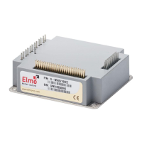
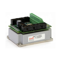
Details weight, dimensions, and mounting method of the Gold Whistle.
Lists electrical parameters like supply voltage, current, and power ratings.
Details the isolated DC source requirements and input voltage/power for control supply.
Lists main features like STO, Digital I/O, Feedback, and Communication options.
Specifies operating ambient temperature, humidity, altitude, shock, and vibration limits.
Lists main standards the Gold Whistle servo drive complies with, including safety and performance.
Details the steps for unpacking the Gold Whistle and verifying its type and condition.
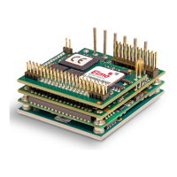
Describes the power stage and control stage connection and the importance of a low-impedance plane.
Refers to another manual for details on the COMRET connection.
Explains the purpose of the PE terminal for chassis connection and EMI common plane.
Details the topology for connecting PE, PR, and COMRET for safe operation.
Illustrates the PCB layout zones for power conductors and control/communication signals.
Explains the meaning of various wiring symbols used in the manual.
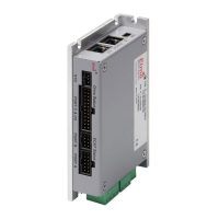
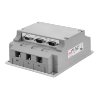
Lists the nine connectors on the Gold Whistle, their types, functions, and locations.
Details the pin assignments for the motor power connectors for brushless and brushed DC motors.
Details the pinout and connection procedure for the main power input.
Details the pinout and connection procedure for the control supply.
Illustrates the power supply connection diagram for the 200V power rating.
Explains the single power supply requirement for the 100V rating and recommends a filter.
Describes using a single DC supply for logic and main power, with optional diode coupling.
Details the functions of Connector J2, covering feedback, analog inputs, and communication protocols.
Explains sensor inputs supported by Port A, including digital hall sensors and encoders.
Provides a recommended connection diagram for incremental encoders to Port A.
Shows the connection diagram for Hall sensors to Port A.
Lists supported absolute encoder types and provides connection diagrams for Endat, Biss, SSI.
Describes the connection diagram for Hiperface encoders via Port A, noting RS232 unavailability.
Details sensors supported by Port B, including incremental, analog, hall sensors, and resolvers.
Provides a recommended connection diagram for incremental encoders to Port B.
Shows the connection diagram for interpolated analog encoders to Port B.
Provides the connection diagram for resolvers to Port B.
Describes Port C's function for emulated encoder output.
Explains the two types of analog inputs: differential ±10V (J2) and single-ended (J1).
Details the internal interface and circuit for Analog Input 1 using Connector J2.
Describes the interface for single-ended Analog Input 2 using Connector J1.
Illustrates the standard RS232 connection diagram incorporating a transceiver.
Shows the USB network diagram, noting the shield connection to COMRET.
Describes EtherCAT slave functionality and connection with RJ-45, including LED indicators.
Displays CAN connectivity diagrams and notes on termination resistors.
Details the functions of Connector J1, covering digital I/O, analog inputs, LEDs, and STO.
Describes the TTL voltage level for digital inputs and their connection diagram.
Details the isolated open collector and open emitter digital outputs with connection diagrams.
Shows the TTL option connection for the STO input interfaces.
Refers to another section for details on the EtherCAT Status Indicator.
Explains the system setup and initialization process using Elmo's EASII software.
Lists heat dissipation capability, thermal time constant, and shut-off temperature.
Presents graphical data on power dissipation versus motor current.
Explains how to use the heat dissipation charts to determine if a heat-sink is needed.
| Communication | EtherCAT, CANopen |
|---|---|
| Feedback | Resolver, Encoder |
| Supported Motors | Linear |
| Safety | STO (Safe Torque Off) |
| Control Modes | Current, Velocity, Position |
| Protection Features | Overvoltage, Undervoltage, Overcurrent, Overtemperature |
| Storage Temperature Range | -40°C to 85°C |