PIPEFITTINGS
Allpipettingsaremadevia22mmcompression
ttingsdirectlytotheunit.Thettingsarethreaded
3/4”BSPmaleparallel,shouldthreadedpipe
connectionsberequired.
COLDFEED
A22mmcoldwatersupplyisrecommended,however,
ifa15mm(1/2”)supplyexists,whichprovidessufcient
ow,thismaybeused(althoughmoreownoise
maybeexperienced).
Astopcockorservicingvalveshouldbeincorporated
intothecoldwatersupplytoenablethecylinderand
itsassociatedcontrolstobeisolatedandserviced.
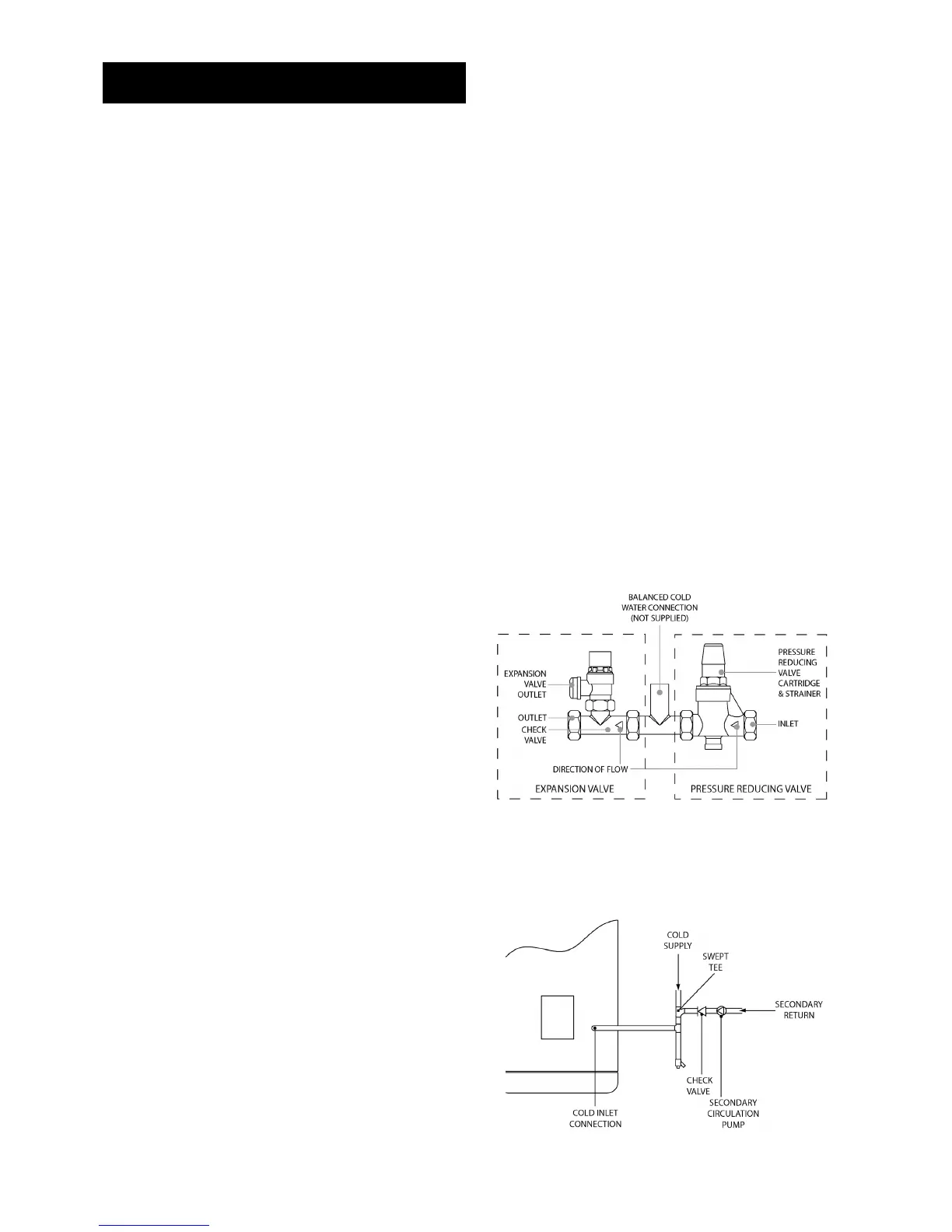
COLDWATERCOMBINATIONVALVEASSEMBLY
The2-piececoldwatercombinationvalveassembly
(seeFig.2)canbelocatedanywhereonthecold
water mains supply prior to the expansion vessel
(seeFig.6Page10)butthetwopiecesdonothave
tobeinstalledtogether.
The pressure reducing valve incorporates the
pressure reducer and strainer and the expansion valve
incorporatestheexpansionandcheckvalves.Ensure
that the valves are installed in the correct order
andorientation.Noothervalvesshouldbeplaced
betweentheexpansionvalveandthecylinder.A
connectioncanbemadebetweentheexpansionand
pressurereducingvalvestoprovideabalancedcold
waterconnection.Theexpansionvalveconnection
mustnotbeusedforanyotherpurpose.
DRAIN TAP
Asuitabledrainingtapshouldbeinstalledinthecold
watersupplytothecylinderbetweentheexpansion
valve(seeFig.6Page10)andtheheaterataslowa
levelaspossible.Itisrecommendedthattheoutlet
pointofthedrainpipeworkbeatleast1metrebelow
theleveloftheheater(thiscanbeachievedby
attachingahosetothedraintapoutletspigot).
EXPANSIONVESSEL
The expansion vessel accommodates expansion
thatresultsfromheatingthewaterinsidetheunit.
Theexpansionvesselispre-chargedat0.35MPa
(3.5bar).Theexpansionvesselmustbeconnected
betweentheexpansionvalveandthecylinder(see
Fig.6Page10).Thelocationoftheexpansion
vessel should allow access to recharge the pressure
asandwhennecessary,thiscanbedoneusing
anormalcarfootpump.Itisrecommendedthat
theexpansionvesselisadequatelysupported.An
expansionvesselwallmountingbracketissupplied
forthispurposeandshouldbetted.
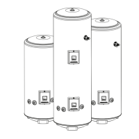
SECONDARYCIRCULATION
Ifsecondarycirculationisrequireditisrecommended
thatitbeconnectedtothecylinderasshown (see
Fig.3page5)via a swept tee joint into the cold
feedtotheunit.Asweptteejointisavailableasan
accessory(ordercodeno.5133565).
Thesecondaryreturnpipeshouldbein15mmpipe
andincorporateacheckvalvetopreventbackow.
AsuitableWRASapprovedbronzecirculation
pumpwillberequired.Onlargesystems,dueto
theincreaseinsystemwatercontent,itmaybe
necessarytotanadditionalexpansionvesseltothe
secondarycircuit.Thisshouldbedoneifthecapacity
ofthesecondarycircuitexceeds10litres.
Pipe capacity (copper):
15mmO.D.=0.13l/m(10litres=77m)
22mmO.D.=0.38l/m(10litres=26m)
28mmO.D.=0.55l/m(10litres=18m)
NOTE:SecondarycirculationisNOTrecommendedfor
directelectricunits.
OUTLET
Thehotwateroutletisa22mmcompressiontting
locatedatthetopofthecylinder.Hotwaterdistribution
pipeworkshouldbe22mmpipewithshortrunsof
15mmpipetoterminalttingssuchassinksand
basins.Pipesizesmayvaryduetosystemdesign.
INSTALLATION GENERAL
Fig.2:Coldwatercombinationvalveassembly
Fig.3:Secondarycirculationconnection