3. Operating location
The length of the inlet and outlet section must be at least twice the nominal diameter
for reasons relating to measuring accuracy.
The inlet section must be designed as a straight pipe section with the same nominal
diameter as the meter.
Flow
disturbanc
es
resulting
from:
Typical inlet
sections
Pipe sections
installed at a
distance of
2D upstream
of the meter
inlet
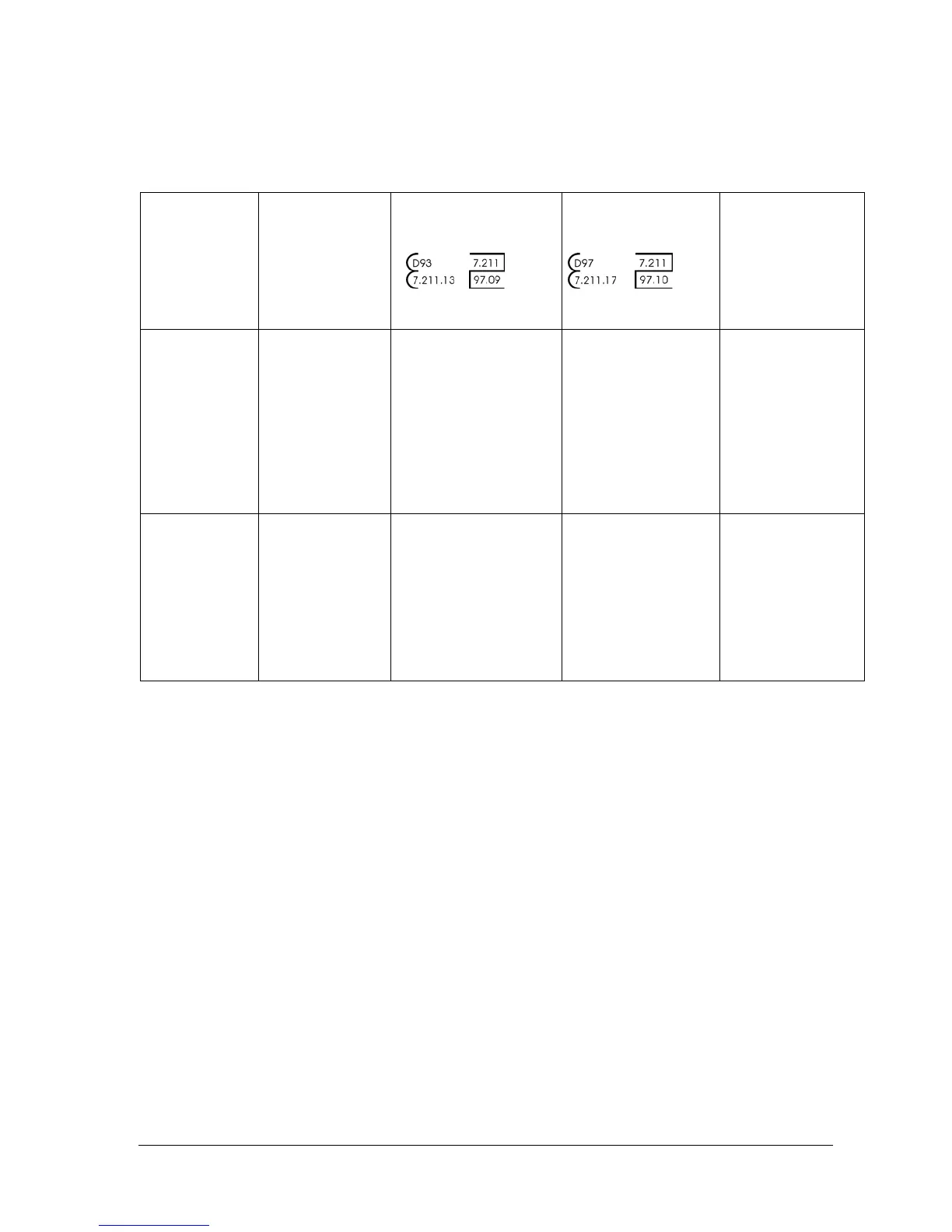
TRZ
PTB approval
symbol
TRZ2 / TRZ-IFS
PTB approval
symbol
Q
Minor
disturbanc
es
- single
manifolds
- twin
manifolds
- diffuser
and
- contractor
s
L ≥ 2D
DN 50 – DN 150
No flow conditioner
DN 200 – DN 600
Flow conditioner
(e.g. BLN 1)
No flow conditioner
if L ≥ 5D
L ≥ 2D
No flow
conditioner
L ≥ 5D
Major
disturbanc
es
- Pressure
regulators
for gas
- Other
restrictor
devices
L ≥ 2D
Flow conditioner
(e.g. BLN 1)
L ≥ 2D
No flow
conditioner
L ≥ 5D
Flow
conditioner
recommended
If you ..
- wish to mix in odorisation agents or
- use solenoid valves,
please always fit them only downstream of the meter. Otherwise, the device may be
damaged.
The flow through the meter must be free of vibration/pulsation in order to avoid
measuring errors.
Compliance with the specified operating and ambient conditions as indicated on the
type label is absolutely essential for safe operation of the meter.
The gas may not contain suspended particles > 50 µm. In addition, the gas must be
dry. Otherwise, the meter may be damaged.
In the case of new installations, we recommend temporarily installing a cone strainer
(mesh size 250 µm) to protect the meter. The strainer should be removed after
approximately 4 weeks.
All rights reserved. Subject to technical modification. Page 5 of 13
 Loading...