Operating Instructions for
Temperature Controller ELT-GP1
Page 9 of 10
6.
Optional Features
6.1 Other housing designs
Another housing model is available for ELT-GP1 for connection of heaters with two cold ends,
which has the necessary Pg-cable glands.
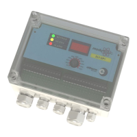
6.2 Digital temperature display (ELT-ONA)
The three-digit temperature display is limited to a range of -51 to +870 °C .
The following settings are displayed with the digital display module:
- Actual temperature of the heater.
- Temperature set-point and bottom (Low Limit) or top (High Limit) temperature limit in the
respective setting mode of the controller (see chapter 5 ‘Settings And Operation’).
- Error messages:
Bottom or top temperature limit (Low Limit, High Limit) not
reached or exceeded respectively.
Short in the temperature probe
(for Pt100 only)
Conductor broken in the temperature probe
Install the digital temperature display as follows:
Before you install the digital temperature display in the controller, disconnect the controller
from the power supply.
• Remove the transparent cover of the housing.
• Screw the front plate off the controller.
• Insert the additional PCB in the space provided for it (see Fig. 4). Proceed with extreme
caution when doing so. Make sure that none of the plug connections are bent or damaged.
• After putting it into place, secure the PCB with locking screws at the threaded bolts
provided for this purpose on the PCB.
• Now screw the new front plate with window onto the controller.
6.3 Analogue Output (ELT-OAA)
When retrofitting an analogue output, we will supply you with the required plug-in board.
To install the plug-in board, proceed as described in chapter 6.2 ‘Digital Temperature Display’!
After installation, the connections are active for analogue output (Terminals 17, 18 and 19, see
‘Terminal Connection Plan’).
 Loading...