Operating Instructions for
Temperature Controller ELT-GP1
Page 3 of 10
1.
Product Description
1.1 Function
In control and monitoring mode, the unit regulates connected heaters to a given set-point (i.e.
target temperature). Monitoring is done based on preset temperature limits. If a limit is
exceeded or is not reached, potential-free contacts are switched (K3). The unit can be
configured for four different types of controller in the factory.
1.2 Control and Display
eltherm
Germany
modu
ELT-GP1
BETRIEB
HEIZEN
ALARM
20°
0°
100°
80°
60°
40°
c
d
e
f
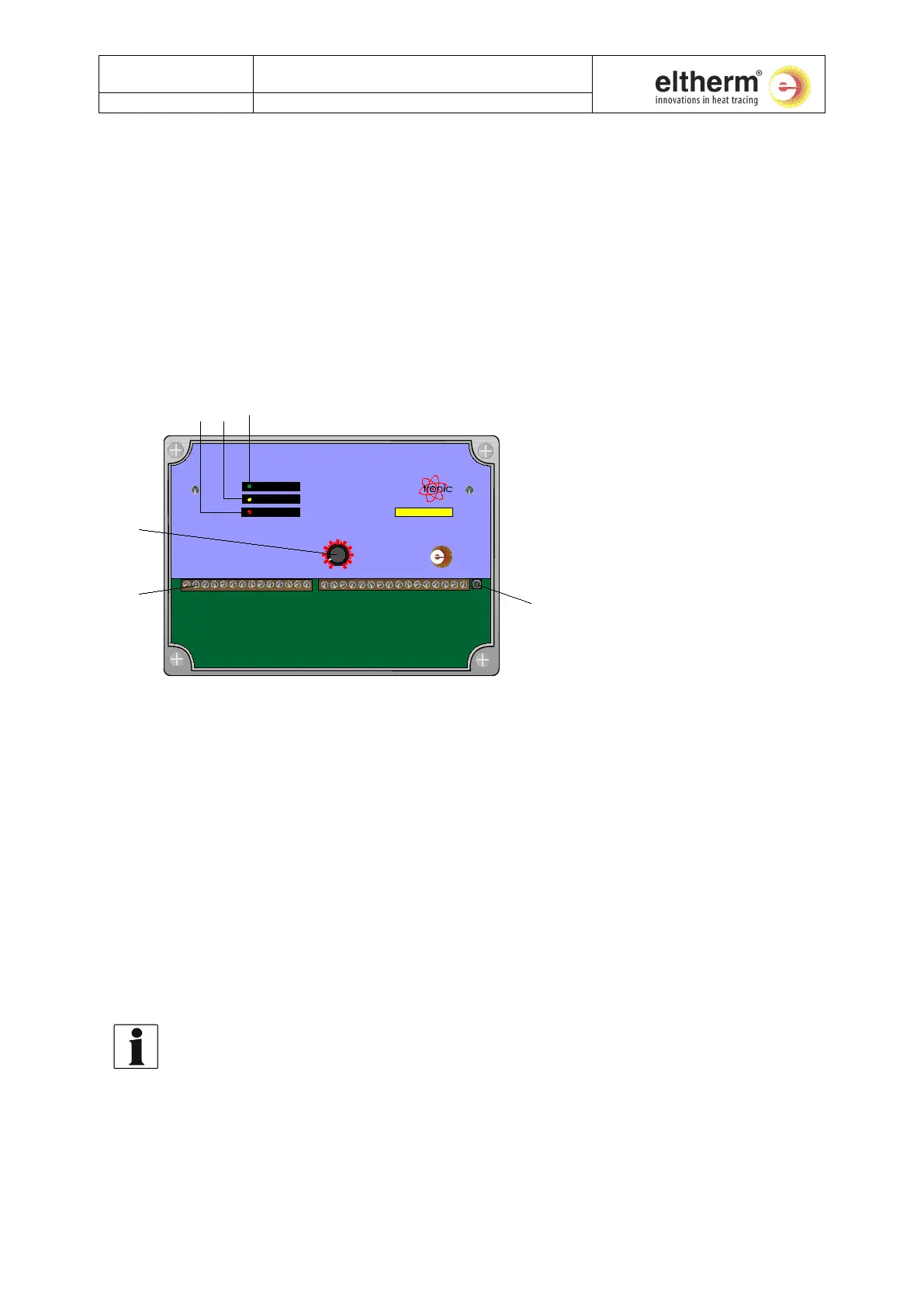
Fig. 1: Control and display
Pos. 1: Potentiometer for adjusting the set-point.
Pos. 2: Terminal strip for all inputs and outputs (see chapter 2.4 ‘Terminal Connection Plan’).
Pos. 3: Control key:
To switch the display from actual to target (set-point) value (if optional display is
present).
To input the bottom temperature limit (Low Limit) and the top temperature limit (High
Limit) for the permissible actual temperature.
Pos. 4: LED ‘Operation’. Lights up green when input voltage is present.
Pos. 5: LED ‘Heat’. Lights up yellow when the heater is switched on.
Pos. 6: LED ‘Alarm’
Lights up red when there is a fault at the temperature probe.
Flashes if the preset temperature limit is exceeded or is not reached.
The LED´s ‘Heat’ and ‘Alarm’ have another meaning when adjusting the set-point (refer to
chapter 5 ‘Settings and Operation’).
 Loading...