42
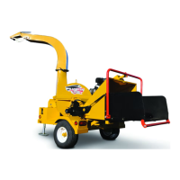
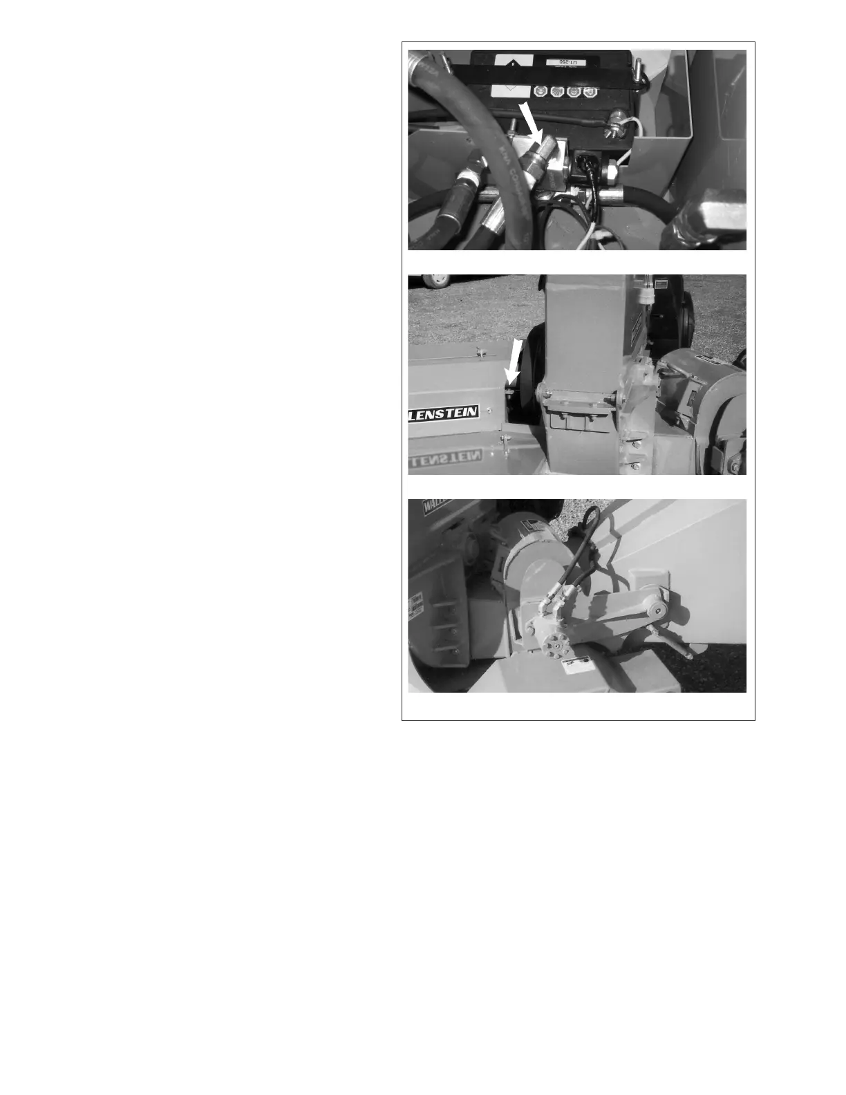
Fig. 29 HYDRAULIC SYSTEM
17. Hydraulic System:
The chipper is designed with a self-con-
tained hydraulic system with a tank, pump,
valves, motors and appropriate hoses.
Pressurized oil is used to power the feed
rollers. It also allows the feed roller drive
system to be part of the material feeding
system.
A hydraulic pump is driven from the front
engine stub shaft and is plumbed to the
adjacent hydraulic tank. A sensor on the
rotor shaft measures the rotor speed. The
controller slows or stops the the feed roll-
ers until the shaft speed increases to the
required RPM. A valve in the circuit controls
and meters the amount of oil owing to each
feed roller hydraulic motor.
Sensor
Roller Drive Motor
Valve Attached