Installation
880 Operation Manual Issue 7 EMC INDUSTRIAL GROUP LTD Page 21 of 25
Alarm Relay (Option)
Alarm output contacts are on terminals 20 and 21 and are rated at 240Vac, 2 amp
load.
When an alarm occurs, the contacts close and remain closed until the ALARM
CANCEL key is pressed.
Thermocouple
Connect positive lead to terminal 14 and negative lead to terminal 15.
Ensure thermocouple extension or compensating cable is separated from power
cabling by at least 50mm, as described in Cable Separation, page 19.
Use the correct extension or compensating cable to extend the probe leads, and
ensure cable is wired with correct polarity i.e. positive lead of exten-
sion/compensating cable connects the probe positive terminal to the controller
positive terminal. If the extension/compensating cable is reverse wired, the kiln
may over fire by as much as 100°C.
If unsure of cable polarity, disconnect from probe and twist the ends together.
Leave the other end connected to terminals 14 and 15 of controller. Apply heat to
the twisted ends and observe temperature reading on display. If the reading in-
creases, the cable is connected correctly to controller. However if the reading de-
creases, the cable is reversed and should be rewired correctly.
Note If Thermocouple burns out or wiring breaks display will show
If Thermocouple is reverse connected, the temperature reading will
decrease to -50°C, (the kiln temperature is actually rising to +50°C),
then at that point the heating will be cut off and the display will show
.
Resistance Thermometer – 3 Wire
This is the preferred method that compensates for temperature errors caused by
cable loop resistance.
Use three core cable connected to terminals 13, 14 and 15. It is important wires
connected to terminals 13 and 14 join together only at the resistance thermometer
end of the cable and not at the controller terminals. Terminal 15 connects by itself
to the other end of the resistance thermometer.
Ensure probe cable is separated from power cabling by at least 100mm, as de-
scribed in Cable Separation, page 19.
Resistance Thermometer – 2 wire
This method of connection requires only a twin conductor cable however it suffers
from temperature reading inaccuracies. For every 0.39 ohms loop resistance in the
cable 1°C will be added onto the real temperature measured. Also temperature
change of the cable affects the temperature reading accuracy. For each 20 °C rise
in cable temperature the error caused by cable length is increased by approxi-
mately 10%.
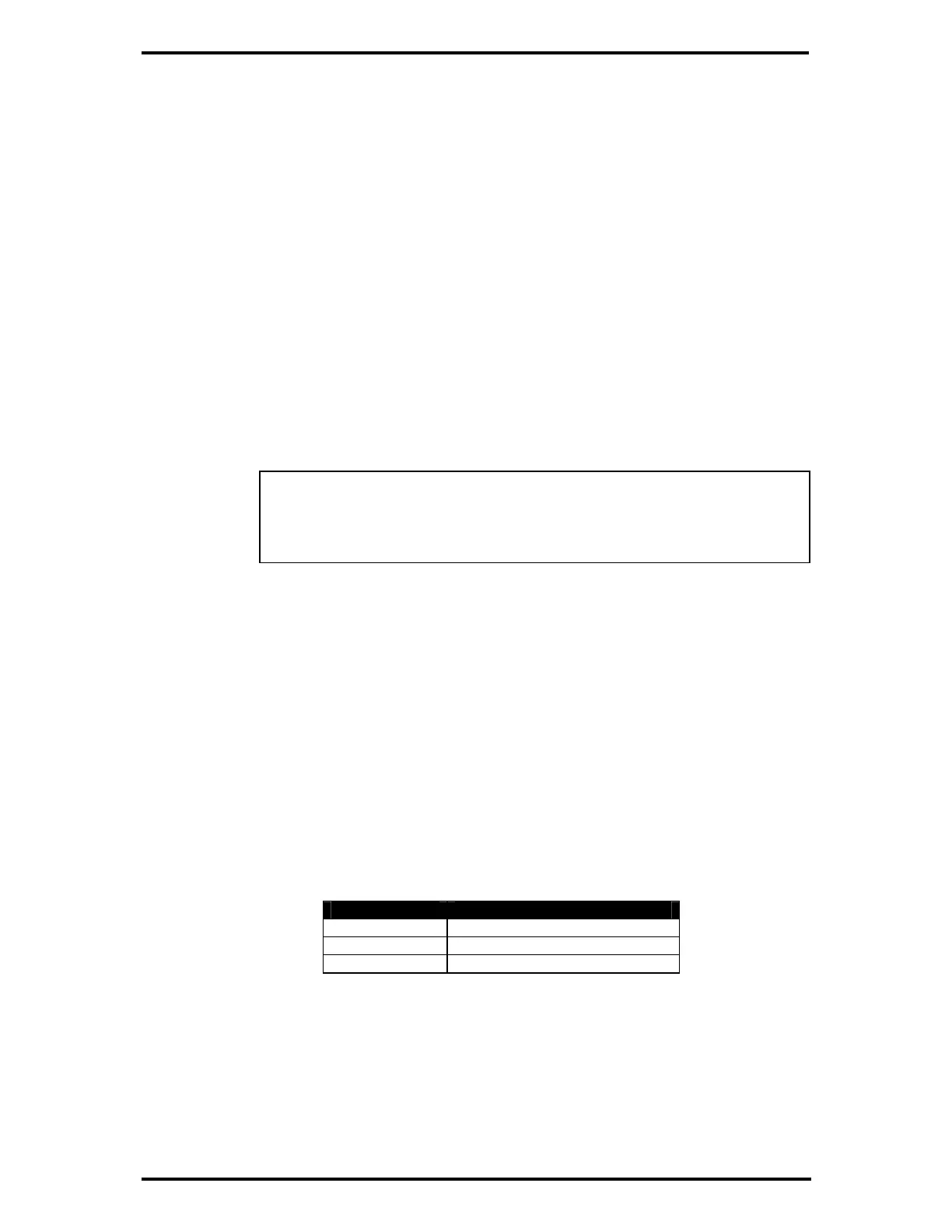
Wire Size mm
2
Cable Length m For 1°C error
0.50 5.50
0.75 8.25
1.00 11.00
Loop terminals 13 and 14 together at the controller terminals and connect terminals
14 and 15 to the resistance thermometer
Ensure probe cable is separated from power cabling by at least 50mm, as de-
scribed in Cable Separation, page 19.