Link control card
s (LCCs)
Optional disk arr
ay enclosures (DAE-AXs) do not include SPs, but use
link control card
s (LCCs) to support additional disk capacity. The LCCs
in each DAE-AX con
nect to expansion ports on SPs or other LCCs with
serial-attache
d SCSI (SAS) expansion cables to create a redundant
back-end bus tha
t can support both SATA and SAS drives. Each LCC
includes a disp
lay indicating the enclosure address of the DAE-AX; the
addressisassi
gned automatically by the system. LCCs also include a
service port co
nnector. An LCC receives input from the previous SP
or LCC on the bu
s through a primary connector (marked by a circle
symbol) and ca
n pass input to the next LCC on the bus through an
expansion co
nnector (marked by a diamond symbol).
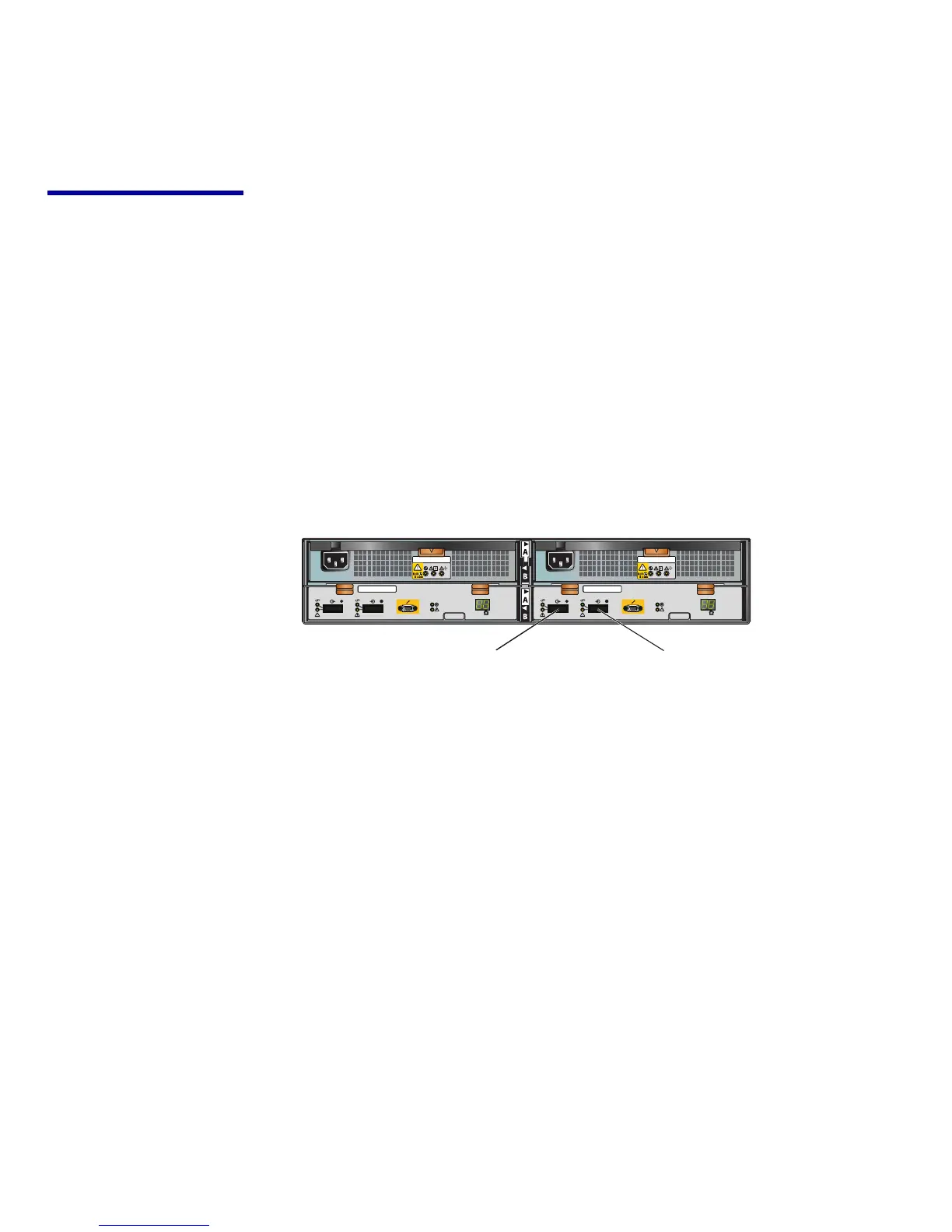
Figure 7 shows
a DAE-AX with two LCCs below the power/cooling
modules.
CL3927
REV: AXX
*AXX*
P/N: 118031924
*118031924*
S/N: VVVYYWWRRRRR
*VVVYYWWRRRRR*
REV: AXX
*AXX*
P/N: 118031924
*118031924*
S/N: VVVYYWWRRRRR
*VVVYYWWRRRRR*
046-003-042_A03
#
FRU Label
REV: AXX
*AXX*
P/N: 118031924
*118031924*
S/N: VVVYYWWRRRRR
*VVVYYWWRRRRR*
046-003-042_A03
#
FRU Label
REV: AXX
*AXX*
P/N: 118031924
*118031924*
S/N: VVVYYWWRRRRR
*VVVYYWWRRRRR*
Expansion Primary
Figure 7 DAE-AX (rea
rview)
8
Hardware and Operational Overview