8 DD670, DD860, and DD890 Hardware Overview
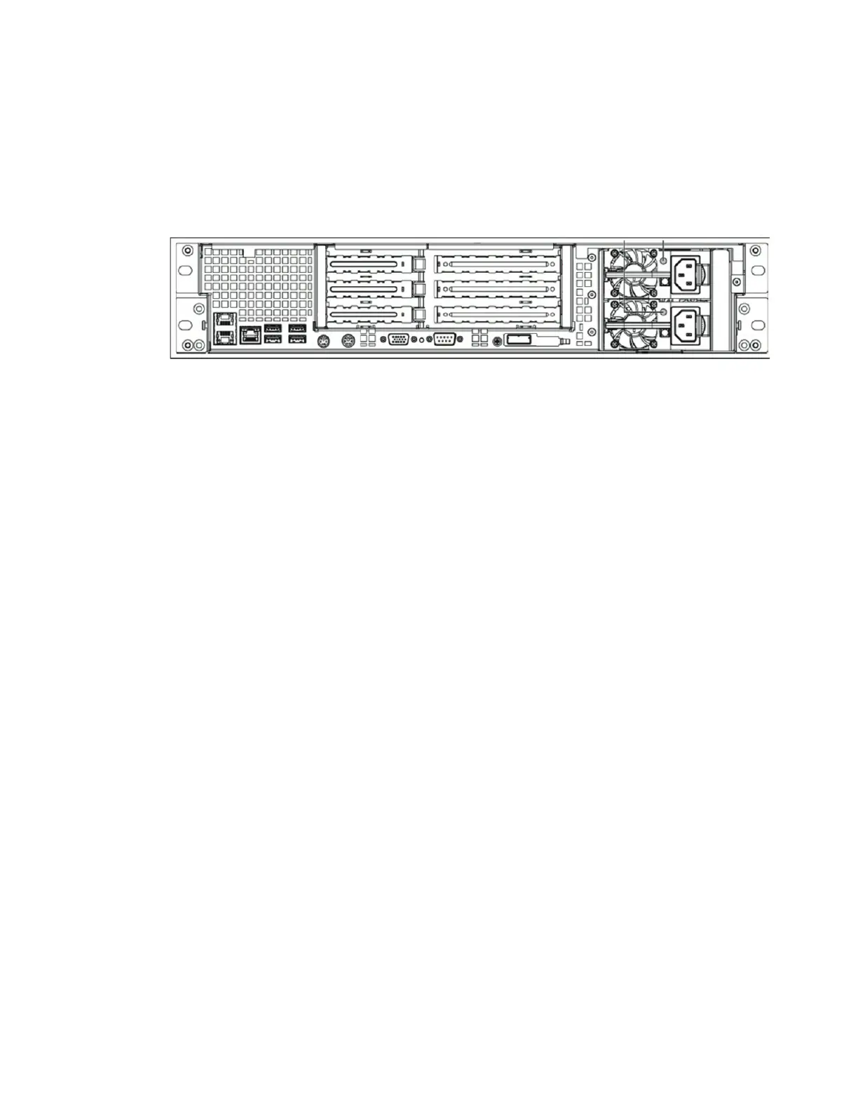
Back Panel
The back panel has the following major functional areas (see Figure 1):
• Power Supply Units
• Hardware Interfaces
• System card interfaces (see “PCI Cards and Slot Assignments” on page 9)
Figure 1: Back Panel
A sticker on the back panel (not shown in Figure 1) shows the system MAC address.
Power Supply Units
The systems have two power supply units. Each power unit has an LED that glows green
when the unit is functional. The LED glows amber if the unit has failed, but still has
power. The LED blinks amber if the power supply does not have AC power. The LED
flashes green when the Data Domain system is turned off but the unit is still plugged in
to a live power source. The LED is dark if the unit has no power.
The two power cords, plugged into the power supply outlets, are held in place by use of
cable restraint ties attached to each power supply.
Hardware Interfaces
The hardware interfaces (see Figure 2) enable you to connect to the system through a
serial console, monitor, and keyboard, or through an Ethernet connection.
The pair of Ethernet interfaces at the left—eth0a and eth0b—are for data transfer to the
Data Domain system or for administrative access over a network. Both Ethernet
interfaces are 1000 Base-T Gigabit copper ports with RJ45 connectors that can accept
10/100 Base-T or Gigabit connections. The single 10/100 Base-T Ethernet port to the right
of the pair of Ethernet ports is used for system maintenance only.
Each Ethernet connection has two LEDs, one on each side of the connector. The left LED
is the Link/Activity LED. When it is dark, the port has no live connection. It glows green
when a link is established and flashes green with transmit/receive traffic. The right LED
is the Speed LED. It indicates 1 Gbps when amber, 100 Mbps when green, and 10 Mbps
when off.