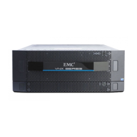
VNX5500 Block and File product description
VNX5500 Hardware Information Guide 11
• Two management modules per DME (or, one per Data Mover)
• Two power supply/cooling (fan) modules per CPU module
◆ One to two 1U Control Stations. Each Control Station consists of the following features:
• Intel 2.0 GHz single core Celeron processor with 800-MHz front side bus (FSB) and
512 KB cache
• 2 GB of RAM
• One 250-GB SATA hard drive
• Two rear-mounted USB ports and one front-mounted USB port
• Four RJ-45 10BASE-T/100BASE-TX/1000BASE-T network interface connectors
(located on the rear panel)
• Two integrated serial ports, one for laptop/console redirection and one for the
CallHome modem
• One DVD-ROM drive
• Two Ethernet (RJ-45) extension cables
◆ Expansion of up to fifteen 3U, 15 (3.5-inch) DAEs (a maximum of 240 disk drives), up
to nine 2U, 25 (2.5-inch) DAEs (a maximum of 250 disk drives), or up to a combination
of three 4U, 60 DAEs (2.5- or 3.5-inch) and three 3U, 15 (3.5-inch) DAEs (a maximum
of 240 disk drives)
When calculating the number of drives for your Block and File (Unified) VNX5500 platform,
the 3U DPE is included in the total drive slot quantity of 240 or 250 drives. If the total drive
slot quantity exceeds 240 or 250, you will not be able to add another DAE. Refer to
“Disk-array enclosure” on page 71 for more information about the available expansion
DAEs for the Block and File (Unified) VNX5500 platform.
◆ Any required cables including LAN cables, modem cables, and serial DB-9 cable.
◆ Mounting rails with hardware
◆ Front bezel with VNX5500 badge

 Loading...