30 VNX5500 Hardware Information Guide
System component description
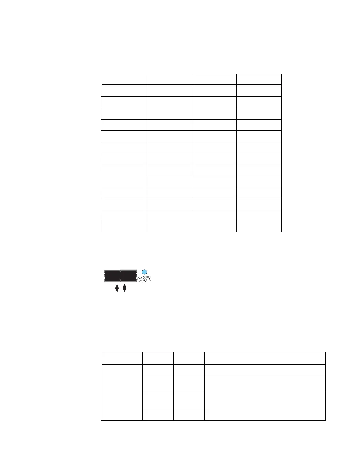
Table 13 lists the SP 6-Gb/s SAS port pin signals used on the connector.
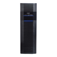
SP 6-Gb/s SAS port LEDs — Figure 19 shows an example of the SP 6-Gb/s SAS 0 x4 port
LED—a bi-color (blue/green) LED to the right of the connector—that indicates the
link/activity of the SAS port.
Figure 19 Example of the SP 6-Gb/s SAS 0 x4 port LED
Table 14 describes the SP 6-Gb/s port LEDs.
Table 13 SP 6-Gb/s SAS port connector pinout
Pin Signal Pin Signal
A1 GND B1 GND
A2 Rx 0+ B2 Tx 0+
A3 Rx 0- B3 Tx 0-
A4 GND B4 GND
A5 Rx 1+ B5 Tx 1+
A6 Rx 1- B6 Tx 1-
A7 GND B7 GND
A8 Rx 2+ B8 Tx 2+
A9 Rx 2- B9 Tx 2-
A10 GND B10 GND
A11 Rx 3+ B11 Tx 3+
A12 Rx 3- B12 Tx 3-
A13 GND B13 GND
0 X4
6Gb SAS
0 x4
VNX-000278
Table 14 SP 6-Gb/s SAS port LEDs
LED Color State Description
Link/activity Blue On All lanes are running at 6 GB/s
Green On One or more lanes is not running at full speed or
disconnected
Alternating
Blue/Green
Blinking Port is being marked by the host
—OffNot connected


 To Next Page