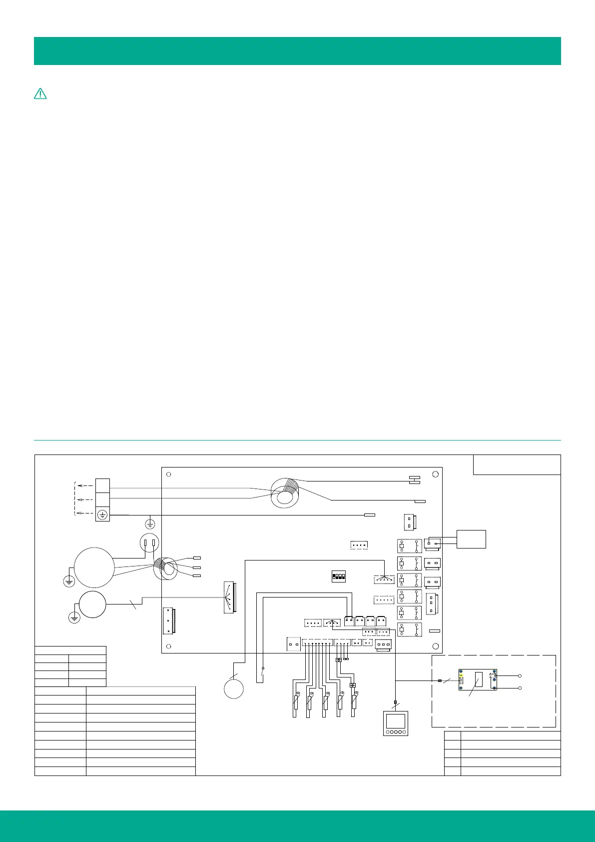
ELECTRICAL CONNECTIONS
24
WARNING
• Only a qualified and trained professional should handle the
electrical connections.
• The heat pump power supply circuit must have a reliable ground
connection, and both power supply and external grounding wires
should be eectively connected.
• The trained installer is responsible for testing the circuit and
making the final connections.
PRECONNECTION & REGULATIONS
• When installing the heat pump, electrical work must adhere to
local supply authority regulations and AS3000 standards.
• The heat pump power rating is fixed at 15 amps, so the mains
power supplying the unit should have a minimum 16 amps circuit
breaker installed.
• Please note that this heat pump includes an over-temperature
control cut-out. It is absolutely essential that the water heater
is never operated without this safety device connected to the
circuit. Any resetting or replacement of this device should only be
undertaken by a qualified electrical contractor.
• According to AS/NZS 60335-1 Clause 7.12.2, a disconnection
feature must be incorporated into the fixed wiring, following the
wiring rules.
• Fuse: 260V, 16A.
• Wiring should be carried out by professional installation technicians
following the provided circuit diagram.
• Arrange the layout of power and signal lines neatly, ensuring
they do not interfere with each other or come into contact with
connecting pipes and valve bodies.
• Ensure that the unit's power lines match the specified require-
ments; do not use wires that do not conform to the specifications.
• After completing all wiring construction, carefully inspect it before
switching on the power supply.
• If the supply cord is damaged, it should be replaced by the
manufacturer, a service agent, or a similarly qualified person to
prevent any potential hazards.
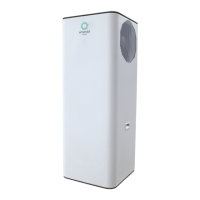
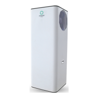
EE-HWS-A1-220(-1), EE-HWS-A1-270(-1) & EE-HWS-A1-320(-1)
V G A B
T4 T6
T1 T2 T3 T5
B
A
U
V
W
PE
AC-N
AC-L
HPS
EXV1
D03
D06
D07
RD
RD
4WV
5
EXV
T1
T2 T3
T5
T4
HPS
4
C o ntro l l e r
U
V
W
Y/GN
N
L
XT1
240V/~ /50Hz
Power In
WH
WH
RD
BU
COMP
U
V
W
MF
5
COMP
Compressor
MF
Motor Fan
4WV
4 way valve
EXV Electronic Expansion Valve
Coil temperature sensor
Exhaust temperature sensor
HPS
High pressure switch
Suction temperature sensor
Ambient temperature sensor
BU
BR
GN
BLUE
BROWN
GREEN
Y
YELLOW
WIRE COLOR CODE
WH
RD
BK
WHITE
RED
BLACK
OR
ORANGE
Inlet temperature sensor
T1
T2
T3
T5
T4
AP1
BU
RD
BU
32190001000666
Y/GN
Y/GN
BU
OP
BU
RD
RD
BU
WH
15V
GND
310V
VSP
FG
BK
WH
XT1 Termianl
AP1
Control panel
KA1
Relay
OP
Overheat protector
AC-L
AC-N
CN1
CN2
AP2
Th e p owe r l ive
pa ss ed thro ugh
th e m ag net ic ri ng
4
AP2
Power Detection Module
BU
RD
AP1.D09
1 2
ON
3 4
D09
WIRING DIAGRAM


 To Next Page