Pressure Controls Series PS1 / PS2
Emerson Climate Technologies GmbH
Pascalstrasse 65 I 52076 Aachen I Germany
www.climate.emerson.com/en-gb Date: 30.03.
2022
OI_PS1(2)_A1_A2L_EN_DE_FR_ES_IT_RU_Rev11_0715180.docx
General information:
For application in refrigeration systems and heat pumps.
The device has a potential ignition source and has not
been qualified according to ATEX standards. Installation
only in “non-explosive location”.
Safety instructions:
• Read operating instructions thoroughly. Failure to
comply can result in device failure, system damage or
personal injury.
• This product is intended for use by qualified personnel
having the appropriate knowledge and skills like trained
according to EN 13313 or a specific training for
flammable refrigerants.
• Flammable refrigerants require special handling and
care due to its flammability. Sufficient ventilation is
required during service of the system.
• Contact with rapidly expanding gases can cause
frostbite and eye damage. Proper protective equipment
(gloves, eye protection, etc.) has to be used.
• Ensure that the system is correctly labeled with applied
refrigerant type and a warning for explosion risk.
• In a severely contaminated system, avoid breathing acid
vapors and avoid contact with skin from contaminated
refrigerant / lubricants. Failure to do so could result in
injury.
• Before opening any system make sure pressure in
system is brought to and remains at atmospheric
pressure.
• Do not release any refrigerant into the atmosphere!
• Do not exceed the specified maximum ratings for
pressure, temperature, voltage and current.
• Ensure that the system piping is grounded.
• Before installation or service disconnect all voltages
from system and device.
• Observe and avoid mechanical damage of housing in
order to maintain protection class.
• Do not use any other fluid media without prior approval
of EMERSON. Use of fluids not listed could result in:
- Change of hazard category of product and
consequently change of conformity assessment
requirement for product in accordance with European
Pressure Equipment Directive 2014/68/EU.
• Ensure that design, installation and operation comply
with European and national standards/regulations.
• For flammable refrigerants only use valves and
accessories approved for it!
Function
Fig. 1a: automatic reset function:
• PS1/PS2 Pressure switches are equipped with SPDT
snap action contacts switching from 1-2 to 1-4 on rising
and from 1-4 to 1-2 on falling pressure.
Fig. 1a
Fig. b: manual reset function for low pressure reset /
Fig. 1c: manual reset function for high pressure reset:
• PS1/PS2 with manual reset (high pressure/low pressure
reset): Reaching the preset switching point contact 1-4
switches to 1-2 (low pressure switch) or from 1-2 to 1-4
(high pressure switch) and locks in this position. After the
pressure rises or drops by a fixed differential the switch
can be reset by pushing the reset button.
Fig. 1b
Fig. 1c
Mounting location:
Any direction except upside down
Installation: (Fig.2)
• PS1/PS2 controls may be installed by using a mounting
plate or as a wall-mounted device against a flat surface.
• Use universal thread M4 or UNC8-32 mounting holes for
installation via mounting plate.
• Use the standard mounting holes at the backside for wall
mounting.
• Use mounting screws supplied with control.
• Mounting screws must not penetrate control backside by
more than 8 mm to ensure proper operation.
• Do not use PS1/PS2 in pulsating operating conditions!
In order to achieve protection class IP44, the following
instructions must be observed:
• Cover must be closed and cover screw fastened
• Control must be mounted against a flat surface so that all
openings on the housing backside are fully covered
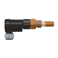
Pressure connection: (Fig. 3)
• Connection of the pressure side depends on the exact
model / pressure connector.
• When connecting PS1/PS2 to the hot gas line of a
refrigeration system, a pipe, capillary or flexible tube of at
least 80 mm shall be used to allow sufficient temperature
drop between refrigeration line and pressure switch
bellows.
Threaded connection:
• Connectors A & C: Do not apply torsional load to
pressure connector; use second spanner to counter-
balance torque when tightening pressure connection.
• K-type connectors: use copper gasket supplied with control.
Brazing connection:
• Perform the brazing joint as per EN 14324.
• Before and after brazing clean tubing and brazing joints.
• Minimize vibrations in the piping lines by appropriate
solutions.
• Do not exceed the max. surface temperature of 70 °C!
Pressure Test:
After completion of installation, a pressure test must be
carried out as follows:
- according to EN 378 for systems which must comply with
European pressure equipment directive 2014/68/EU.
- to maximum working pressure of system for other
applications.
Tightness Test:
Conduct a tightness test according to EN 378-2 with
appropriate equipment and method to identify leakages
from joints and products. The allowable leakage rate must
be according system manufacturer’s specification.
Warning:
• Failure to pressure test or tightness test as
described could result in loss of refrigerant, damage
to property and/or personal injury.
• The tests must be conducted by skilled personnel
with due respect regarding the danger related to
pressure.
Electrical connection: (Fig. 4)
• Entire electrical connections have to comply with local
regulations.
• Wire size must match the electrical load connected to
the switch contacts.
• Ensure that the cables are mounted without tension;
always leave the cable a bit loose.
• Ensure that cables are not mounted near sharp edges.
• Do not bend or mechanically stress the cable outlet,
maintain a clearance of 20 mm to neighboring parts .
• Feed cables through rubber grommet at switch bottom.
• Optionally, the rubber grommet may be replaced by a
standard PG 13.5 cable gland.
• Connect wires to terminals by taking into account switch
functions as shown in Fig. 1a to Fig. 1c.
• Fasten terminal screws with torque 1.2 Nm max.
• For electronic applications with low electrical loads
(voltage < 24 V and current <50 mA) gold plated contacts
are recommended.
Setpoint adjustment: (Fig. 5)
• PS1/PS2 pressure switches come with individually
adjustable range and differential depending on the exact
model.
• Manual reset switches always have a fixed differential.
• Use a flat screw driver or a 1/4” refrigeration (square)
wrench to adjust setpoints as described below.
• Adjust upper setpoint using the range spindle.
• Adjust lower setpoint by turning the differential spindle.
Upper setpoint – Differential = Lower setpoint
Fig. 5
(3) Differential = constant
(7) Differential = variable
(4) Turning range spindle
(8) Turning differential
spindle
• A separate gauge must be used for exact adjustment of
the setpoints. The integrated display scale can only be
used for obtaining approximate settings.
• When changing the upper setpoint the lower setpoint
must be re-checked.
• Refer to the Emerson catalogue or Technical Information
for standard factory settings.
Manual reset / Universal reset: (Fig. 6a-c)
• Manual reset (external): press the reset button (1) as
indicated by Fig. 6a.
• Manual reset (internal): remove the housing cover and press
the reset button (2) as indicated by Fig. 6b.
• Note that the reset is ‘trip-free’, i.e. reset is only possible
if the pressure has reached its reset threshold.
• Universal reset: remove the cover and change the
universal toggle to the desired position (manual (3) or
auto reset (4).(Fig. 6c)
Check- out lever: ((5) Fig. 4 & Fig. 7)
• Use the check-out lever to manually override the
electrical contact position for testing out the system.
• Use the check-out lever on low pressure switches to
manually override the electrical contact position for
evacuating the refrigeration system.
Service / Maintenance:
• Disconnect electrical power before service.
• In case of repair work or replacing the control always use
a new gasket. (K-Types)
• According to EN 378-4 during each periodic
maintenance, tightness tests shall be carried out at the
relevant part of the refrigerating system. This shall apply
where appropriate following any repair.