Do you have a question about the Emerson ASCO 185 Series and is the answer not in the manual?
Defines DANGER, WARNING, and CAUTION symbols used in the manual for hazard communication.
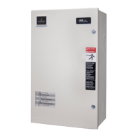
States that installation of the ATS must be performed by an experienced licensed electrician.
Advises protecting the ATS from construction grit and metal chips during installation.
Warns about the importance of the insulator backing piece for 260 and 400 Ampere transfer switches.
Covers protection by circuit breakers and NEC requirements for ATS power connections.
Warns to turn off all power before wiring the transfer switch to prevent electrocution.
Advises installing cable spacers correctly to prevent cable loosening during short circuits.
Advises ensuring safe conditions before using the Transfer Test button.
Emphasizes turning off all power before manually operating the transfer switch.
Step-by-step procedure to test the ATS's electrical operation and transfer sequences.
Illustrates the step-by-step sequence of events during a utility failure and generator startup.
Addresses why the Utility Acceptable light may not illuminate and provides solutions.
| Manufacturer | Emerson ASCO |
|---|---|
| Series | 185 |
| Category | Switch |
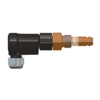
| Type | Pressure Switch |
| Function | Pressure Sensing |
| Connection Type | Threaded |
| Housing Material | Aluminum |