Series 185
381333–319 D
Namepl ate
The Transfer Switch nameplate includes data for
each specific ASCO Series 185 ATS. Use the ATS
only within the limits shown on this nameplate.
Catalog Number Identification
A typical Catalog Number is shown below with its
elements explained . T h e example is for a D–d esig n ,
2 pole, 200 A, 220–240 V, in Type 1 indoor enclosure:
D 185 A 2 200 F 4 C
Phase Poles
Neutral
Amperes Voltage Controller Enclosure
A –standard
4 –standard
C –Type1
M –Type3R
2 –singleØ
F 220--- 240
260
230
100
200
4X
–if
accessories
ordered
400
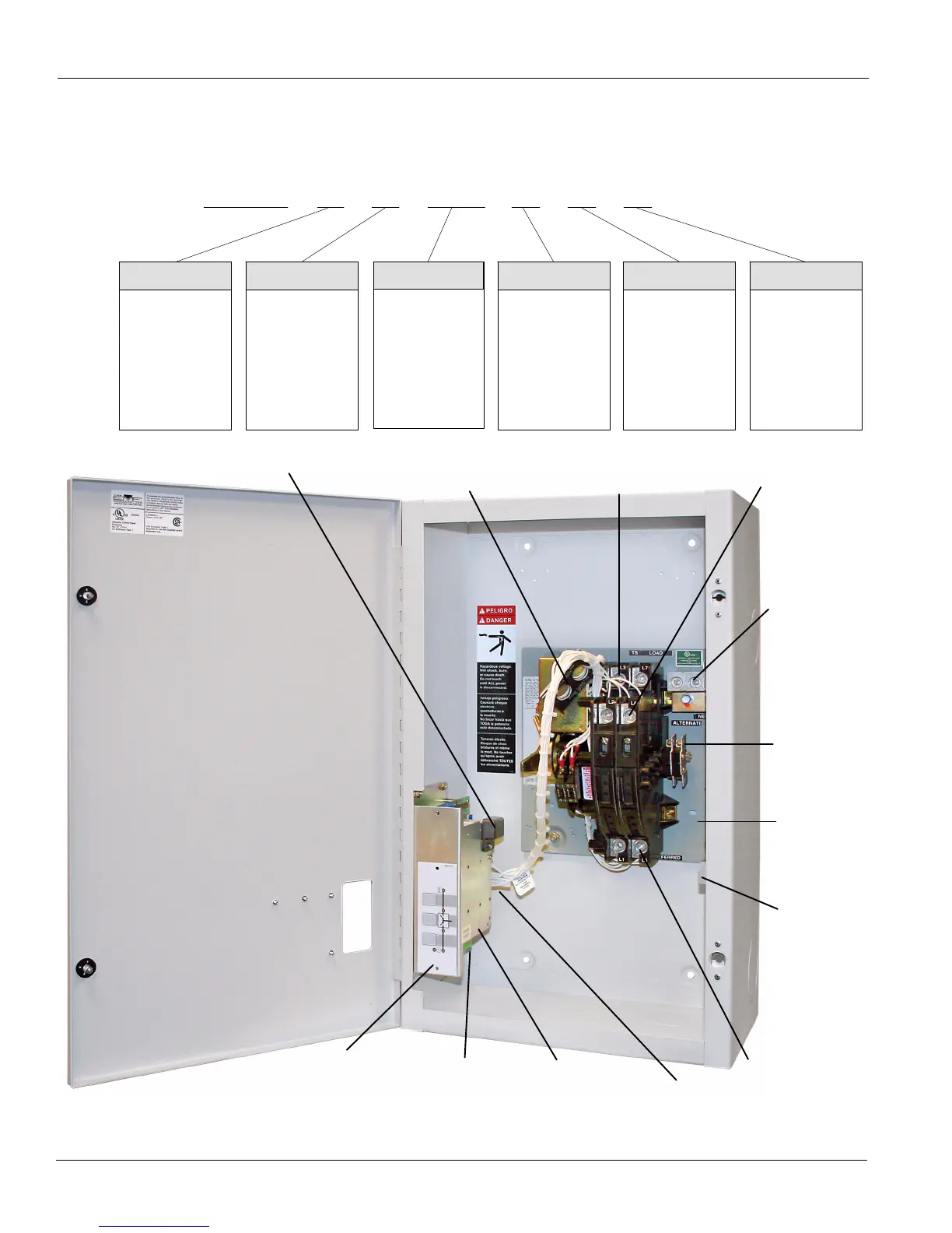
Transfer
Switch
Controller
emergency
power
connections
membrane
controls
200 ampere size in typical enclosure with location of customer connections
terminals
for optional
switch
position
contacts
(shown
installed)
load power
connections
cable spacers
(see INSTALLA TION)
utility power
connections
neutral
connections
ground
connections
generator
control
connections
clock battery
harness plug
 Loading...