FB2100/FB2200 Flow Computer CPU Enclosure & Electronics Field Replacement Guide
D301803X012
November 2020
15
6.
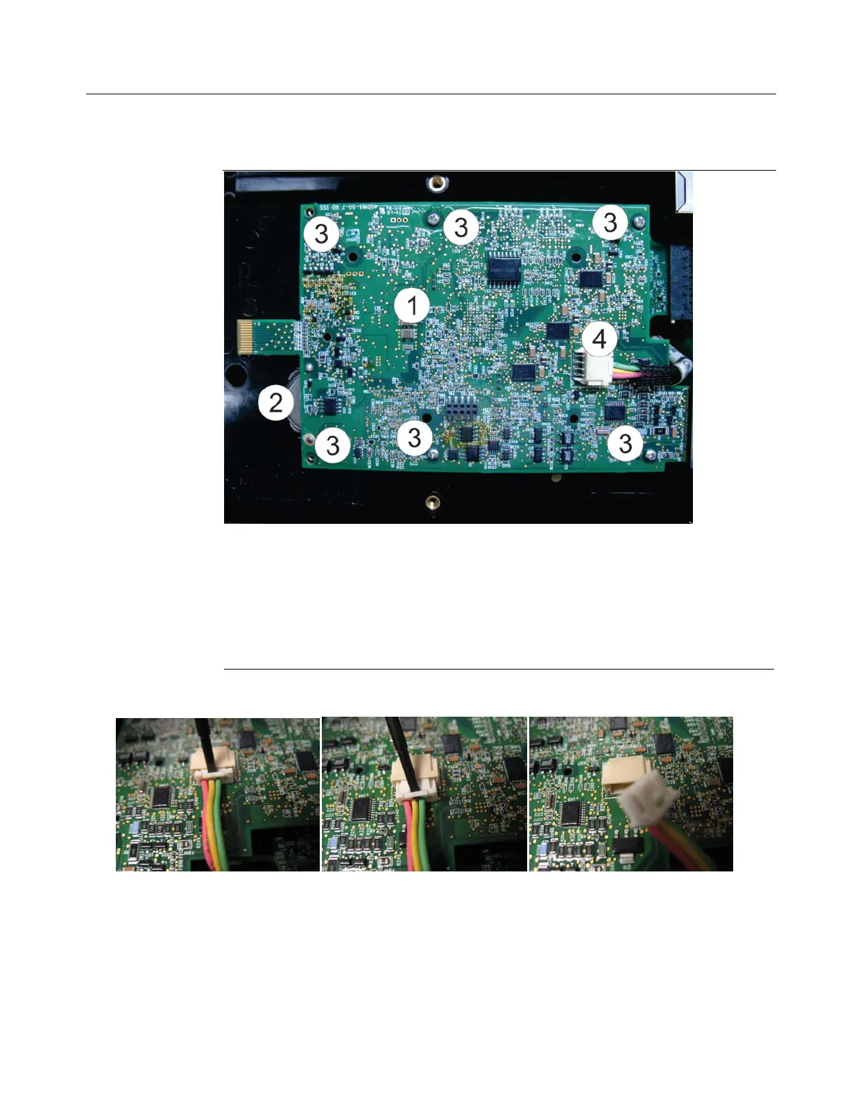
Use a #1 Phillips-head screwdriver to remove the screws that hold down the CPU board. Save
the screws. If you have the 6-channel expansion I/O board installed, there are 6 screws; if the
board is not present, there are 4 screws.
Screw locations. There are six screws (if you have the 6-channel expansion
I/O board installed underneath) or four screws (without the board).
: The two left-most screws in this picture have been removed to ease
removal of the adapter board.
Connector for intermediate cable to sensor module
7.
Use a small flat head screwdriver to push the intermediate cable connector off its mating
connector on the CPU board.
8.
Gently slide the CPU board out of its connector on the connectivity board.
9.
If the CPU board itself is to be replaced with a new CPU board, take the SRAM backup battery
out as you will need it for the new replacement CPU board. Otherwise, leave the battery in
the board.

 Loading...


