EasyManua.ls Logo

Emerson Control Link Refrigeration System Controller User Manual

Emerson Control Link Refrigeration System Controller
8 pages
To Next Page IconTo Next Page
Page #1 background imageLoading...
Page #1 background image
technical bulletin
Document Part # 026-4600 Rev 3 23-APR-2008 Page 1 of 8
©2007 Emerson Climate Technologies Retail Solutions, Inc. This document may be photocopied for personal use.
Visit our website at http://www.emersonretailsolutions.com/ for the latest technical documentation and updates.
CO
MP
U
TER PR
OC
E
SS
CO
NTR
O
L
S
®
Control Link RSC Installation Instructions
Overview
The Control Link Refrigeration System Controller (CL-RSC) is an electronic device that can control all functions
of a single-compressor refrigeration system, including refrigeration, defrost, and alarming. Scheduled defrost and
case light control is also possible with the addition of an expansion real-time clock module (P/N 618-2082, avail-
able separately).
The CL-RSC reads discharge air and defrost termination temperature from sensors mounted in the case. The CL-
RSC may control two external relays (compressor plus one configurable relay) directly from its two onboard dry-
contact relay outputs, or it may use a pluggable expansion output board (P/N 618-1120 for compressor control, or
618-2085 for refrigeration solenoid control) for activating case system components.
NOTE: For information about networking Control Link RSC with E2, refer to Technical Bulletin 026-4602
available on the Internet at http://www.emersonretailsolutions.com/library
.
Mounting
Main Module / Relay Expansion Board
The Control Link main module and relay expansion boards are designed for mounting on a refrigerated case or in
an enclosure near the case. The output board connects to the main module with a ribbon cable and therefore should
be mounted directly below the main module using the attached stand-off bracket. Figure 1 shows module dimen-
sions, and Figure 2 shows relay expansion board dimensions.
Figure 1 - Control Link Module Mounting
Figure 2 - Expansion Board Mounting
Question and Answer IconNeed help?

Do you have a question about the Emerson Control Link Refrigeration System Controller and is the answer not in the manual?

Emerson Control Link Refrigeration System Controller Specifications

General IconGeneral
BrandEmerson
ModelControl Link Refrigeration System Controller
CategoryController
LanguageEnglish

Summary

Overview

Product Introduction

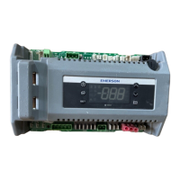
Introduces the Control Link RSC, an electronic device controlling refrigeration systems, defrost, and alarms.

Mounting Instructions

Module and Expansion Board Mounting

Details dimensions and mounting for the Control Link main module and relay expansion boards.

System Specifications

Environment and Remote Display

Covers operating conditions, storage temps, and remote display mounting/wiring.

Wiring and Connections

Power Wiring

Guides for connecting power to the Control Link module with various output boards.

Sensor Wiring

Details wiring for case temperature and defrost termination sensors to the module.

Output Board Wiring Details

618-2085 Board Wiring

Wiring for defrost, fans, aux, and compressor relays on the 618-2085 output board.

618-1120 Board Wiring

Wiring for defrost, fans, aux, and solenoid/contactor on the 618-1120 output board.

Pressure Switch Configuration

Pressure Switch Wiring

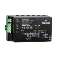
Instructions for wiring a pressure switch to the relay output board for compressor control.

CL-RSC Operation

User Interface Overview

Explains the display, status LEDs, and control buttons for operating the CL-RSC.

Modes of Operation

Describes start-up, normal refrigeration, and alarm handling during operation.

Defrost and Fail-Safe Procedures

Defrost Cycle Management

Details initiation, termination, and drip time for defrost cycles.

Fail-Safe Mode Operations

Explains compressor fail-safe and output board fail-safes during power/comm loss.

Auxiliary Relay Control

Auxiliary Function Control

Lists various functions the auxiliary relay can control, like lighting or alarms.

General Parameter Settings

Accessing General Parameters

Guide to accessing and navigating general parameters for system setup.

Advanced Parameter Settings

Accessing Advanced Parameters

Instructions for entering advanced programming mode and setting the password.

System Restore and Alarms

Restore to Factory Defaults

Procedure to reset the CL-RSC to factory default setpoints using the dedicated button.

Alarm Codes and Clearing

Describes CL-RSC alarm codes, actions, and how to clear active alarms.

Related product manuals