Document Part # 026-4600 Rev 3 23-APR-2008 Page 3 of 8
©2007 Emerson Climate Technologies Retail Solutions, Inc. This document may be photocopied for personal use.
Visit our website at http://www.emersonretailsolutions.com/ for the latest technical documentation and updates.
Control Link RSC Installation Instructions
technical bulletin
CL-RSC Onboard Outputs
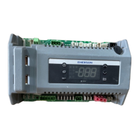
If using CL-RSC without an expansion board, wire the outputs to the two-wire terminals
on the right side of the control unit, as shown in Figure 6. Each of these output points are
rated to a maximum of 3A @ 250V. For loads greater than 3A, use the outputs to energize
external relays for compressors, defrost, and case lights.
Expansion Board Wiring
Both types of relay output boards connect to the Control Link main module using an 8-pin
ribbon cable. Plug the cable onto the Expansion Board connector at the bottom of the main
module.
Relay and Pressure Switch Wiring (618-2085 Output
Board)
Defrost, Fans, and Aux Relay (
Using spade lugs, connect the defrost heater(s), case fans, and
auxiliary output (either case lights or an alarm device) to the
three relays on the left side of the relay output board as shown in
Figure 7. Refer to Table 1 for relay ratings.
Compressor Relays
The Control Link uses two relays on the output board to control
the compressor. Line voltage must be connected to the Line 1 and
Line 2 connectors on relays 1 and 2 respectively. The Load 1 and
Load 2 connectors are wired to the compressor. Figure 7 shows
the wiring diagram. Refer to Table 1 for relay ratings.
Pressure Switch Wiring
If desired, a pressure switch may be used to deactivate the compressor if a high/low suction pressure condition occurs.
Remove the jumper wire and connect this switch to the dual screw-terminal Pressure Switch connector located in the mid-
dle of the relay output board. See Figure 7. If not used, these terminals must be jumpered in order for the board to work.
The pressure switch must be N.C. (normally closed) type.
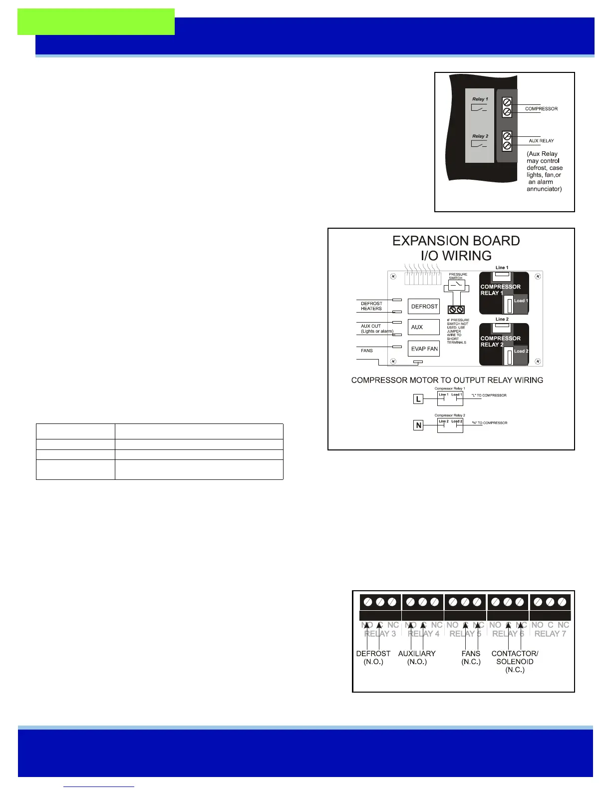
Relay Wiring (618-1120 Output Board)
Use the Form C contactors on the output board points labeled RELAY
3 through RELAY 6 to connect the defrost, auxiliary, fans, and sole-
noid or contactor. Refer to Figure 8, and refer to Table 2 for relay rat-
ings and fail-safe positions.
Relays Output Board 618-2085
Defrost and Aux 10A at 120VAC
Fan 208-230VAC 2 FLA 4 LRA
Compressors 208-230VAC 10FLA 60LRA
115VAC 13FLA 86LRA
Table 1 - Relay Ratings (Output Board 618-2085)
Figure 6 - CL-RSC Outputs
Figure 7 - Expansion Board Output Wiring
Figure 8 - Expansion Board Output Wiring