Document Part # 026-4600 Rev 3 23-APR-2008 Page 7 of 8
©2007 Emerson Climate Technologies Retail Solutions, Inc. This document may be photocopied for personal use.
Visit our website at http://www.emersonretailsolutions.com/ for the latest technical documentation and updates.
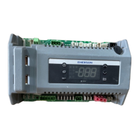
Control Link RSC Installation Instructions
technical bulletin
Advanced Parameters
Advanced parameters are used to change higher-level parameters. Selecting and changing advanced parameters works the
same way as general parameters, except they are accessed in a different way and require entering a different password.
Before changing parameters, clear any active alarms by pressing the Alarm Silence button. Press and hold the UP and
DOWN buttons simultaneously for five seconds to enter advanced programming mode. The display will show APAS. Press
(SET) and use the arrow keys to select the correct password (default is 0000), and press (SET) to enter it.
AdEL
Alarm delay for high/low temp alarm. Temp must remain out of alarm setpoint range for this number of minutes
before an alarm can occur.
06010
Sft
Software revision number. This field is read-only.
Advanced Parameters
Code Description Min Max
Default
rYbd
Selects whether outputs will be controlled from the RSC’s onboard relays (no) or the expansion board (yES).
no yES no
LF
Line frequency (Hz)
50 60 60
r2Fn
Function of the aux relay (relay #2) on the RSC. dEF=Defrost, FAn=case fans, LCon=lighting control,
ALAr=alarm. Visible only when rYbd = no.
dEF ALAr dEF
F C
Temperature units (this affects units for both display and setpoints)
FC F
dIFF
Control temp setpoint differential (deadband around setpoint) in degrees
1101
HSP
High temp control setpoint limit (CSP cannot be set higher than this value) in degrees
-40 100 100
LSP
Low temp control setpoint limit (CSP cannot be set lower than this value) in degrees
-40 100 -40
SI2
Determines type of sensor on input #2 (defr. term). If ntc is selected, input will be used as defrost term; if dGt
selected, input will be used as an auxiliary input (whose function is determined by
SI2d).
ntc dGt ntc
SI2d
If input #2 (defr. term) is dGt, determines function of digital input. SS = setpoint shift (“ON” causes the value of
CSS to be added to set points), IdeF = start manual defrost.
IdeF
SS
IdeF
SI3
Determines type of sensor on input #3. ntc = 10K CPC thermistor, dGT = digital sensor.
ntc dGt ntc
SI3d
If input #3 is dGt, determines function of digital input. SS = setpoint shift (closure causes the value of CSS to be
added to set points),
IdeF = initiate manual defrost.
IdeF
SS
IdeF
CAL1 CAL2 CAL3
Va l ue o f CAL1, CAL2, and CAL3 parameters are added to their respective temp inputs for calibration purposes.
-10 10 0
FAnO
Fan during normal mode. no = on only when compressor is on, yES = always on during normal mode. Visible
only if fan output is present (i.e. expansion board is being used, or
r2Fn=FAn).
no yES no
FANd
Fan during defrost. no = fan off, yES = fan on during defrost. Visible only if the RSC is controlling both fan and
defrost with an expansion board.
no yES no
FOtP
Fan ON temp setpoint. After defrost, temp must fall below this setpoint before fans will be allowed to activate.
Visible only if the RSC is controlling both fan and defrost with an expansion board.
-40 100 32
FdAd
Fan activation delay after defrost, in seconds. (if zero, FOtP is used after defrost; if non-zero, FdAd is
used).Visible only if the RSC is controlling both fan and defrost with an expansion board.
012010
CSUd
Compressor ON delay after power-up (minutes)
01510
COt
Minimum compressor OFF time (minutes)
0155
COnt
Minimum compressor ON time (minutes)
0151
CSFP
Compressor fail-safe period. When case temp sensor fails, compressor will cycle ON/OFF over this period (see
CSFO).
06010
CSFO
Amount of time in the CSFP fail-safe period that the compressor will be ON (minutes).
0605
CSS
Control setpoint shift - value is added to all control and alarm setpoints when a setpoint shift input is closed.
-140 140 0
drt
Minimum time between defrosts, in minutes. Visible if a defrost output is present (using expansion board, or
r2Fn= dEF).
0 120 60
Add
Alarms display disabled. yES = no alarm codes displayed on the RSC. no = alarms enabled.
no yES no
General Parameters
Code Description Min Max
Default
 Loading...