Document Part # 026-4600 Rev 3 23-APR-2008 Page 2 of 8
©2007 Emerson Climate Technologies Retail Solutions, Inc. This document may be photocopied for personal use.
Visit our website at http://www.emersonretailsolutions.com/ for the latest technical documentation and updates.
Control Link RSC Installation Instructions
technical bulletin
Main Module and Expansion Board Environment Specs
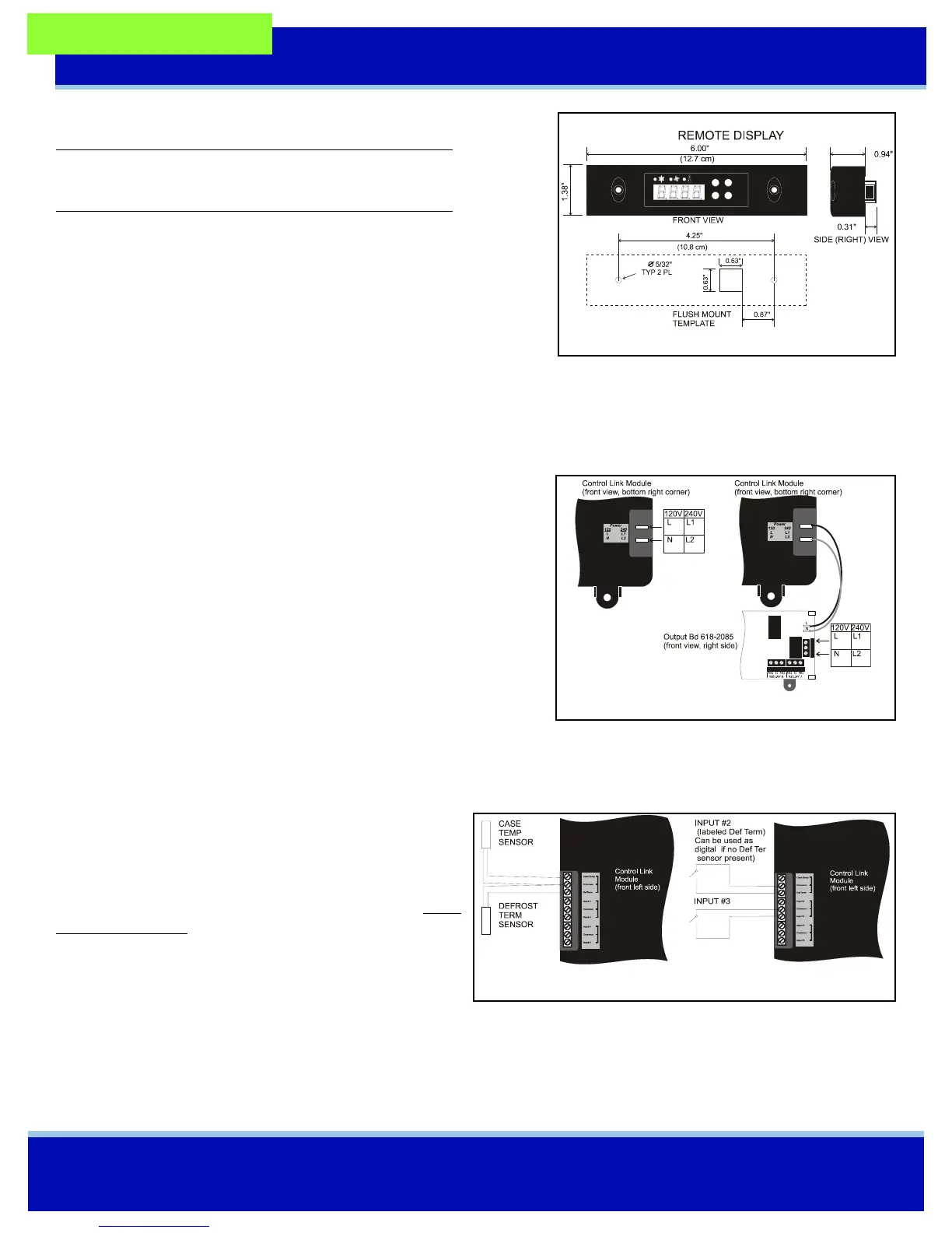
Remote Display Mounting
The remote display is designed to be mounted on an accessible part of a
refrigerated case or enclosure, no more than 25 feet from the main mod-
ule. If flush mounting on a flat surface such as the front of a case or
enclosure, punch a 5/8” square hole in the surface to allow the protrud-
ing RJ45 jack to recess, and then drill 5/32” holes for the mounting
screws using the remote display itself as a template. Figure 3 shows the
dimensions.
Power down the main module before connecting the remote display. Use CAT5 wiring with RJ45 connectors to connect
the Main Module with the Remote Display. Do not exceed a maximum length of 25 feet.
Wiring
Power (Control Link Module without output board, or with
618-2085 output board)
When the Control Link module is used without an output board or with
the 816-2085 output board, connect 120-240 VAC 50-60 Hz line voltage
to the spade lug connectors on the lower right side of the Control Link
module (Figure 4). The expansion board is powered from the CL-RSC
and requires no external power connection.
Power (Control Link Module with 618-1120 output board)
When the 618-1120 output board is used with a Control Link module,
connect the L and N spade lug terminals on the module to the L and N spade lug terminals on the output board (Figure 4).
Connect 120-240 VAC 50-60 Hz line voltage to the screw terminals labeled L and N on the output board. Do not connect
any wire to the middle terminal.
Sensors
Case temperature and defrost termination temperature sen-
sors must be wired to the top three-terminal connector on
the left side of the Control Link module. Use only CPC
NTC 10k thermistors. The defrost termination sensor must
be a 10k thermistor, not a temperature switch. Wire as
shown in Figure 5. Mount the case temp sensor in the dis-
charge air stream for the case. Mount the defrost termina-
tion sensor near the evaporator coil.
Inputs for switches to activate setpoint shift and initiate defrost may be wired to Input 3, and also to the Def Term input
(Input #2) if no defrost termination sensor is being used. The functions of these switches are determined by parameters
SI2d and SI3d in Advanced Parameters.
Operating Temperature: 0 — 60°C (14—140°F)
Operating Humidity: 90% RH non-condensing
Storage Temp: -30—65°C (-22—149°F)
Max Power Consumption: 15W (Control Link w/expansion board)
Figure 3 - Remote Display Mounting
Figure 4 - Control Link Power
Figure 5 - Sensor Wiring