FB2100/FB2200 Flow Computer CPU Enclosure & Electronics Field Replacement Guide
D301803X012
November 2020
20
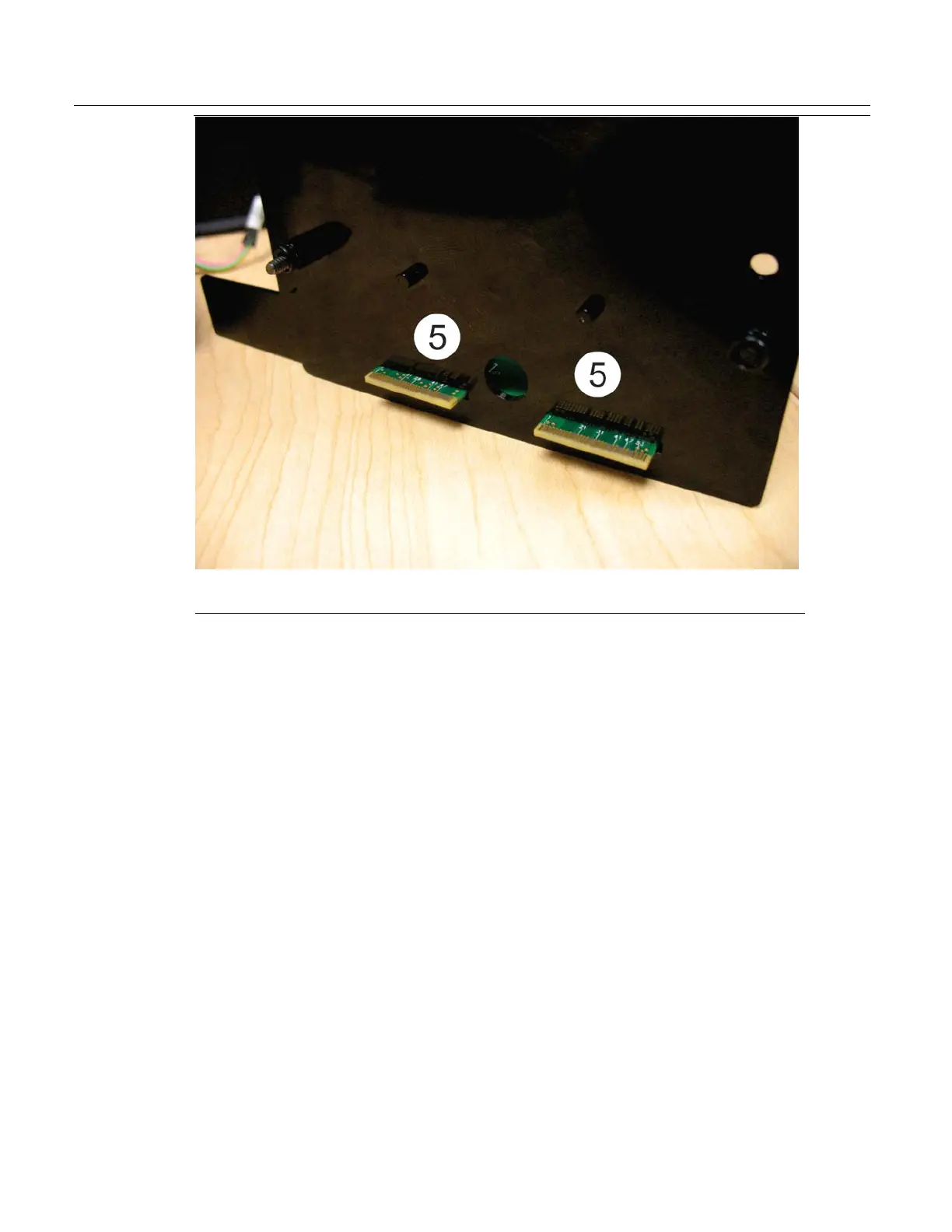
Connectivity board connectors that go through the bottom of the CPU
enclosure to mate with the termination I/O board.
You would remove/replace the connectivity board if it fails, or as a step in the field replacement of the
CPU enclosure (bottom).
Removing the Connectivity Board
1.
Remove the HMI module. See Removing the HMI Module on page 6.
2.
Disconnect the cable between the CPU enclosure and the sensor. See Disconnecting the Cable
Between the CPU Enclosure and the Sensor on page 7.
3.
Detach the CPU enclosure from the battery compartment. See Detaching the CPU Enclosure from
the Battery Compartment on page 7.
4.
Remove the CPU enclosure cover. See Removing the CPU Enclosure Cover (Top) on page 10.
5.
Remove the adapter board. See Removing the Adapter Board on page 12.
6.
Remove the CPU board. See Removing the CPU Board on page 14.
7.
If present, carefully slide the 6-channel expansion I/O board out of its socket off the connectivity
board and set it aside.
8.
Slide the connectivity board out of the CPU enclosure and set it aside.

 Loading...


