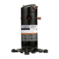
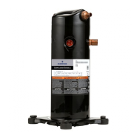
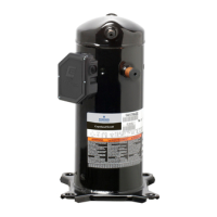
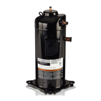
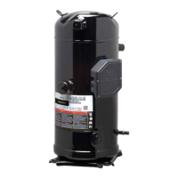
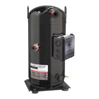
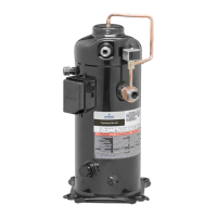
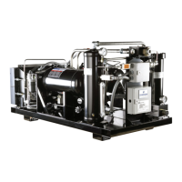
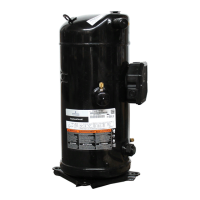
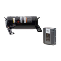
Emerson EVC Drive and Variable Speed
Scroll Set-Up
A quick start guide is available with the Emerson EVC
drive. Application Engineering is available to assist
during any part of this process.
Refrigerant
ZPV066 and ZPV096 compressors are approved for
use with R-410A only. Use of refrigerants other than R-
410A voids the UL recognition of these compressor
models since the motor overload system could be
adversely affected.
Operating Envelope
The compressor operating envelope at each speed
represents the allowable range of operating
conditions for the compressor at the superheat and
subcooling values defined on the envelope. The most
current and updated operating envelopes can be
accessed in Online Product Information at
Emerson.com/OPI. Contact Application Engineering
if desired to operate at different speeds than
published in the operating envelope.
Operating the compressor at evaporating
temperatures that are higher than those specified in
the envelopes for the given speed will result in a
higher oil circulation rate. A higher oil circulation rate
can reduce heat exchanger efficiency and possibly
result in oil pump-out if the system has long
interconnecting piping. Customers that choose to
operate in these higher evaporating temperature
areas should use a compressor sample with a sight-
tube during system development testing to ensure
that an adequate level of oil is maintained in the
compressor sump. Sight-tubed compressors for
monitoring the oil level are available by contacting
Application Engineering.
The lower right boundary of the operating envelope is
the minimum compression ratio required to keep the
scrolls loaded. Operation below this boundary could
result in the compressor intermittently loading and
unloading and noisy operation.
The upper left boundary of the envelope represents
the maximum compression ratio when operating with
20F° (11°C) suction superheat. If the operating
condition approaches this boundary of the envelope
the compressor discharge temperature will begin to
approach the maximum scroll temperature allowed by
the discharge line thermistor.
If operating the compressor below 1800 RPM, an oil
boost cycle is required. Refer to the note in the
operating envelope.
For applications where the voltage is below the rated
minimum voltage, the drive speed may be limited. The
limitation may also be affected by the ambient
temperature.
High Pressure Control
A high pressure control must be used in all
applications.
A high pressure control must be used with these
compressors since they do not employ an internal
pressure relief valve (IPR). The maximum cut-out
setting must not exceed 650 psig (45 bar). The switch
should be wired in series with the unit contactor to
immediately stop compressor operation if there is a
high pressure event. The high pressure control should
have a manual reset feature for the highest level of
system protection. If an auto reset high pressure
control is used, the compressor should be locked out
after three consecutive trips. If a pressure transducer is
used to protect against high discharge pressure events
the transducer and control logic should comply with
U.L. and/or local safety requirements.
Low Pressure Control
A low pressure control is required to protect against
loss of charge and other system fault conditions that
can lead to compressor overheating. A low pressure
cut-out switch located in the suction line with a cut-out
setting no lower than 20 psig (1.4 bar) is required in all
heat pump applications. For air conditioning units, a
cut-out setting no lower than 55 psig (3.8 bar) will
adequately protect against most low pressure faults. A
higher level of protection for air conditioning units can
be realized if the cut-out setting is increased to 95 psig
(6.6 bar) to prevent evaporator coil icing.
Discharge Temperature Protection
Compressor top cap temperatures can be very hot.
Care must be taken to ensure that wiring or other
materials which could be damaged by these
temperatures do not come into contact with these
potentially hot areas.
ZPV066 and ZPV096 compressors do not have an
internal discharge gas temperature protection. In order
for the variable speed drive to operate properly a
thermistor should be attached to the compressor
discharge line as close as possible and less than 6''
(15cm) from the compressor discharge fitting. The
thermistor is designed for a 7/8" (22 mm) line and
 Loading...
