EasyManua.ls Logo

Emerson Copeland Scroll ZPS KC Series - User Manual

Emerson Copeland Scroll ZPS KC Series
11 pages
Print Icon
To Next Page IconTo Next Page
Loading...
© 2017 Emerson Climate Technologies, Inc.
1
TABLE OF CONTENTS
Safety
Safety Instructions .................................................... 2
Safety Icon Explanation ............................................ 2
Instructions Pertaining to Risk of Electrical
Shock, Fire, or Injury to Persons ............................... 3
Safety Statements .................................................... 3
Introduction
How It Works ........................................................... 4
Capacity Control ...................................................... 4
Nomenclature .......................................................... 4
Application Considerations
Operating Envelope ................................................. 4
High Pressure Control .............................................. 5
Low Pressure Control ............................................... 5
Discharge Temperature Protection……………………5
Crankcase Heat ....................................................... 5
Defrost Cycle ........................................................... 5
Unloader Solenoid Wiring ......................................... 5
Standard Wiring with 24 Volts................................... 5
Part-Load Starting .................................................... 6
Application Tests......................................................6
Assembly Line Procedures
Hipot (AC High Potential) Testing ............................. 6
Service Procedures
Unloader Test Procedure with 24 Volts ..................... 6
Unloader Test Procedure with CoreSense ............. 7
Figures
ZPS*KC Modulation Hardware .................................. 4
Operating Envelope .................................................. 8
24 Volt Modulation Control Wiring ............................. 8
Modulation Control Wiring with CoreSense™ ............ 9
Crankcase Heater Location....................................... 9
Tables
Compressor Refrigerant Charge Limits ..................... 10
Solenoid Resistance Value ....................................... 10
Compressor Accessories .......................................... 11
Wiring with CoreSense™ Diagnostics…………………6
AE4-1428 R1
October 2018
6 to 10 Ton ZPS*KC Copeland Scroll™ Two-Stage Compressors
Question and Answer IconNeed help?

Do you have a question about the Emerson Copeland Scroll ZPS KC Series and is the answer not in the manual?

Summary

Safety

Safety Instructions

General guidelines for safe operation and handling of Copeland Scroll™ compressors.

Safety Icon Explanation

Explanation of hazard alert symbols (Danger, Warning, Caution, Notice) used in the bulletin.

Instructions Pertaining to Risk of Electrical Shock, Fire, or Injury to Persons

Detailed safety instructions covering electrical shock, fire, and personal injury hazards.

Safety Statements

Key statements regarding proper use, installation, commission, and maintenance of compressors.

Introduction

How It Works

Explains the modulation mechanism using a 24-volt DC solenoid valve and a 3-way solenoid valve.

Capacity Control

Describes how capacity modulation is achieved by venting gas within the scroll compression process.

Nomenclature

Explains how model numbers relate to compressor capacity and operating conditions.

Application Considerations

Operating Envelope

Details acceptable operating conditions for ZPS*KC compressors, noting part-load limitations.

High Pressure Control

Recommended settings and manual reset for high-pressure cut-out controls.

Low Pressure Control

Recommended low-pressure cut-out settings for heat pumps and air-conditioning units.

Discharge Temperature Protection

Information on Therm-O-Disc™ protection against excessive discharge gas temperature.

Crankcase Heat

Requirement for crankcase heaters in systems exceeding 120% of refrigerant charge limit.

Defrost Cycle

Recommends full-load operation for defrosting to improve efficiency and performance.

Unloader Solenoid Wiring

Notes on the current requirements for the modulation solenoid to ensure proper operation.

Standard Wiring with 24 Volts

Details on how a nominal 24-volt DC coil activates the internal unloader solenoid.

Part-Load Starting

Wiring with CoreSense Diagnostics

Information on CoreSense diagnostics and active protection for modulated compressors.

Application Tests

Assembly Line Procedures

Hipot (AC High Potential) Testing

Guidelines for dielectric strength testing of the modulation solenoid circuit.

Service Procedures

Unloader Test Procedure with Standard 24 Volt Wiring

Methods to verify unloader operation by checking amperage and coil resistance.

Unloader Test Procedure with CoreSense

Procedures to test unloader function with CoreSense, checking voltage and coil resistance.

Overview

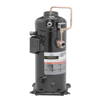
The document describes the 6 to 10 Ton ZPS*KC Copeland Scroll™ Two-Stage Compressors, which are designed for commercial and light commercial applications requiring capacity stage reduction and part-load efficiency.

Function Description

These compressors are two-stage modulated Copeland Scroll™ units that provide capacity control by modulating between full-load and part-load operation. A 24-volt DC solenoid valve inside the compressor controls this modulation. When the solenoid valve is energized, the compressor operates in full-load (100% capacity). When de-energized, it operates in part-load (approximately 67% of full-load capacity). This modulation is achieved by a 3-way solenoid valve that provides pressure to a lift ring assembly, which opens and closes scroll modulation ports. This process vents a portion of the gas in the first suction pocket back to the low side of the compressor, reducing effective displacement. The compressor's single-speed motor continues to run while the scroll modulates, allowing "on the fly" capacity changes without shutting off the motor. The unloaded (part-load) mode is the default, as it's expected to be the most common operating mode and allows for simple two-stage thermostat control in both cooling and heating.

The ZPS*KC compressors are approved for use with R410a refrigerant only. They can operate at full-load capacity throughout their specified operating envelope, though there are limitations in part-load operation.

Important Technical Specifications

  • Capacity Control: Achieved via a 24-volt DC solenoid valve.
  • Modulation: Full-load (100%) when solenoid is energized; part-load (approx. 67%) when solenoid is de-energized.
  • Motor: Single-speed.
  • Refrigerant: R410a only.
  • Control Circuit Voltage: 18 to 28-volt AC or DC for the unloader solenoid.
  • Maximum Solenoid VA: 5 VA.
  • Solenoid Coil Resistance: 1640 Ω for all ZPS*KC models (Table 2).
  • Modulation Solenoid Circuit Current: Must be less than 0.9 mA for the solenoid valve to change from full-load to part-load. Currents greater than 0.9 mA can cause the solenoid to remain in full-load.
  • Hipot Testing (24-volt modulation solenoid circuit): Maximum applied voltage not to exceed 1,000 volts RMS for 1 second at 2.0mA maximum leakage current.
  • High Pressure Control: Recommended cut-out setting not to exceed 650 psig (45 bar) with a manual reset.
  • Low Pressure Control: Recommended cut-out setting no lower than 20 psig (1.4 bar) for heat pumps and 55 psig (3.8 bar) for air-conditioning units.
  • Discharge Temperature Protection: Equipped with Therm-O-Disc™ (TOD) temperature protection, designed to open and route excessively hot discharge gas back to the internal motor overload when internal discharge gas exceeds 290°F (144°C).
  • Internal Pressure Relief Valve: ZPS*KC two-stage compressors do not have an Internal Pressure Relief valve.
  • Crankcase Heater Requirement: Required for systems containing more than 120% of the compressor refrigerant charge limit (Table 1).
    • ZPS67-91KC: Charge Limit: 10 Pounds (4.5 kg); 120% x Limit: 12.0 Pounds (5.4 kg).
    • ZPS104-122KC: Charge Limit: 11 Pounds (5 kg); 120% x Limit: 13.0 Pounds (6 kg).
  • Operating Envelope: Full load operating envelope is provided in Figure 2, showing acceptable condensing and evaporating temperatures.
  • Nomenclature: Model numbers include approximate nominal 60Hz capacity at AHRI operating conditions (45°F/7.2°C evaporating temperature and 130°F/54.4°C condensing temperature).

Usage Features

  • Part-Load Starting: Recommended for all ZPS*KC compressors. Benefits include improved starting during low voltage or flooded start conditions, reduced stress on the motor and scrolls, faster acceleration to full speed, reduced perception of light dimming, and lower inrush current on the 24-volt transformer.
  • Defrost Cycle: Defrosting with the compressor in full-load is highly recommended to shorten defrost time, reduce sound, and aid reversing valve shifting in low outdoor ambient temperatures.
  • CoreSense™ Diagnostics: Available for certain models (Table 3), providing diagnostics, active protection, and modulation features. A simple wiring diagram for CoreSense is shown in Figure 4.
  • Molded Electrical Plug: The external solenoid electrical connection uses a molded plug assembly, which contains a full wave rectifier for AC control circuits. If the control circuit is DC, the rectifier has no effect. Polarity is not critical for DC input.
  • Application Guidelines: Basic application guidelines from AE4-1365 should be followed. Specific differences for ZPS*KC compressors are outlined in the document.

Maintenance Features

  • Safety Instructions: Adherence to U.S. and European Safety Standards is emphasized. Instructions cover electrical shock, pressurized system, burn hazards, and compressor handling.
  • Unloader Test Procedure (Standard 24 Volt Wiring):
    1. Measure compressor amperage while cycling the unloader on and off. An increase in amperage indicates full-load, a reduction indicates part-load.
    2. Measure unloader solenoid coil resistance (should have continuity, not infinite or grounded).
    3. Check molded plug: Apply control voltage (18 to 28 VAC) and measure DC voltage at connectors (15 to 27 VDC). Measure resistance from plug lead to female connectors (one should read zero ohms, the other infinity, then reverse polarity and repeat).
  • Unloader Test Procedure (with CoreSense™):
    1. Measure compressor amperage while cycling Y2 voltage to the module. Observe amperage changes for full-load/part-load transition.
    2. If amperage changes are not observed, remove solenoid plug and test voltage output at the plug (18 to 28 VDC DC). If not, check voltage at "DC Sol" pins of the module.
    3. If correct DC voltage is present, measure unloader coil resistance (should have continuity, not infinite or grounded).
  • Crankcase Heater Installation: Refer to Figure 5 for proper installation, ensuring the connection point straddles the compressor seam weld. Verify correct voltage and proper grounding.
  • Compressor Accessories: Table 3 lists various accessories including mounting kits, crankcase heater junction boxes, grounding screws, molded plugs, flexible metal conduit retainers, CoreSense™ Diagnostics Modules, and discharge line thermostats, along with their part numbers and applicable models.
  • Service Procedures: For general service practices, refer to AE4-1365.

Emerson Copeland Scroll ZPS KC Series Specifications

General IconGeneral
BrandEmerson
ModelCopeland Scroll ZPS KC Series
CategoryAir Compressor
LanguageEnglish

Related product manuals