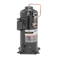
internal unloader solenoid in the ZPS*KC compressors.
The input control circuit voltage must be 18 to 28-volt
AC or DC. The maximum solenoid VA is 5. The
external solenoid electrical connection is made with a
molded plug assembly, see Table 3 for the appropriate
part number. This plug contains a full wave rectifier to
supply direct current to the unloader coil if the control
circuit is AC. If the control circuit is DC, the same plug
with the full wave rectifier can be used as the full wave
rectifier will have no effect on the DC voltage input.
When a DC power source is used, the polarity of the
DC input to the plug isn’t critical. The rectified molded
plug can be sourced from some of the same suppliers
of the molded electrical plug used to power the
compressor motor. A simple wiring diagram is shown in
Figure 3.
Part-Load Starting
There are several benefits associated with starting
the compressors in part-load. Improved starting is
realized during a low voltage and/or flooded start
condition whereby stress on the motor, scrolls,
and 3-way modulation valve is significantly reduced.
Starting in part-load can result in the compressor
starting and accelerating to full speed faster, thereby
reducing the perception of light dimming. Part-load
starting also reduces the inrush current on the 24 volt
transformer. For the highest level of system reliability,
part-load starting is recommended for all ZPS*KC
compressors.
Wired with CoreSense™ Diagnostics
CoreSense provides both diagnostics and active
protection, in addition to modulation features. Please
read 2005ECT-191 for more information on CoreSense
Diagnostics for modulated compressors. A simple
wiring diagram for CoreSense is shown in Figure 4.
See Table 3 for applicable compressor models that
can utilize CoreSense Diagnostics modules.
APPLICATION TESTS
Refer to the Application Tests section of AE4-1365
for the application tests to run to help ensure a reliable
application. Consult with your Emerson Climate
Technologies Application Engineer if interpretation of
application test results are required.
ASSEMBLY LINE PROCEDURES
Hipot (AC High Potential) Testing
Use caution with high voltage and never hipot
when compressor is in a vacuum.
If the 24-volt modulation solenoid circuit is dielectric
(hipot) strength tested, the maximum applied voltage
should not exceed 1,000 volts RMS for 1 second at
2.0mA maximum leakage current.
SERVICE PROCEDURES
Use caution when troubleshooting energized
circuits.
Unloader Test Procedure with Standard 24 Volt
Wiring
If it is suspected that the unloader is not working, the
following methods may be used to verify operation.
1. Operate the system and measure compressor
amperage. Cycle the unloader on and off at ten
second intervals. An increase in compressor
amperage should be observed when switching
from part-load to full-load and a reduction in
compressor amperage should be observed when
changing from full-load to part-load. The percent
change in current depends on the operating
conditions and voltage.
2. Shut off power and remove the control circuit
molded plug from the compressor and measure
the unloader solenoid coil resistance. The
solenoid coil should have continuity and not be
grounded or have infinite resistance. If the coil
resistance is infinite, zero, or grounded, the
compressor must be replaced. See Table 2 for
modulation solenoid resistance values.
3. Check the molded plug.
Voltage check: Apply control voltage to the plug
wires (18 to 28 VAC). The measured DC voltage
at the connectors in the plug should be around 15
to 27 VDC.
Resistance check: Measure the resistance from
the end of one molded plug lead to either of the
two female connectors in the plug. One of the

 Loading...