21°F) allows to adjust possible offset of the probe 4.
SERVICE – OTHERS
LCL Light on during cleaning mode (n, y)
FCL Fan on during cleaning mode (n, y)
MAP Map used during standard operation (1°M, 2°M, 3°M, 4°M) It sets the map used by the
controller among the four possible maps
MP1 Alternate Map enabled by digital input or Modbus command (1°M, 2°M, 3°M, 4°M) It sets
the alternate map enabled by digital input or Modbus command among the four possible maps
CLt Coling time percentage: it shows the effective cooling time calculated by XM600 during
regulation;
tMd Time to next defrost: it shows time before the next defrost if interval defrost is selected;
LSn L.A.N. section number (1 ÷ 8) Shows the number of sections available in the L.A.N.
Lan L.A.N. serial address (1 ÷ LSn) Identifies the instrument address inside local network of
multiplexed cabinet controller.
Adr RS485 serial address (1÷247): Identifies the instrument address when connected to a ModBUS
compatible monitoring system.
br It sets the baud rate among: (96 = 9.6 bit/s; 192 = 19.2 bit/s)
EMU Previous versions emulation (2V8 , 3V8 , 4V2) It allows the controller to be used in a LAN of
controllers with previous versions:
2V8 = it emulates version 2.8
3V8 = it emulates version 3.8
4V2 = it emulates version 4.2
rEL Release software: (read only) Software version of the microprocessor.
SrL Software subrelease: (read only) for internal use
Ptb Parameter table: (read only) it shows the original code of the Dixell parameter map.
Pr2 Access to the protected parameter list (read only).
14. DIGITAL INPUTS
The XM600 series can support up to 3 free of voltage contact configurable digital inputs (depending on
the models). They are configurable via i#F parameter
14.1 GENERIC ALARM (EAL)
As soon as the digital input 1, 2, or 3 is activated the unit will wait for “d1d” or “d2d” or “d3d” time delay
before signalling the “EAL” alarm message. The outputs status doesn’t change. The alarm stops just after
the digital input is de-activated.
14.2 SERIOUS ALARM MODE (BAL)
When the digital input is activated, the unit will wait for “d1d” or “d2d” or “d3d” delay before signalling the
“BAL” alarm message. The relay outputs are switched OFF. The alarm will stop as soon as the digital
input is de-activated.
14.3 PRESSURE SWITCH (PAL)
If during the interval time set by “d1d” or “d2d” or “d3d” parameter, the pressure switch has reached the
number of activation of the “nPS” parameter, the “CA” pressure alarm message will be displayed. The
compressor and the regulation are stopped. When the digital input is ON the compressor is always OFF.
If the nPS activation in the d#d time is reached, switch off and on the instrument to restart normal
regulation.
14.4 DOOR SWITCH INPUT (dor)
It signals the door status and the corresponding relay output status through the “odc” parameter: no =
normal (any change); Fan = Fan OFF; CPr = Compressor OFF; F_C = Compressor and fan OFF. Since
the door is opened, after the delay time set through parameter “d#d”, the door alarm is enabled, the
display shows the message “dA” and the regulation restarts after rrd time. The alarm stops as soon as
the external digital input is disabled again. With the door open, the high and low temperature alarms are
disabled.
14.5 START DEFROST (DEF)
It executes a defrost if there are the right conditions. After the defrost is finished, the normal regulation
will restart only if the digital input is disabled otherwise the instrument will wait until the “Mdf” safety time
is expired.
14.6 RELAY AUX ACTUATION (AUS)
This function allows to turn ON and OFF the auxiliary relay by using the digital input as external switch.
14.7 RELAY LIGHT ACTUATION (LIG)
This function allows to turn ON and OFF the light relay by using the digital input as external switch.
14.8 REMOTE ON/OFF (ONF)
This function allows to switch ON and OFF the instrument.
14.9 FHU – NOT USED
This function allows to change the kind of regulation from cooling to heating and viceversa.
14.10 ENERGY SAVING INPUT (ES)
The Energy Saving function allows to change the set point value as the result of the SET+ HES
(parameter) sum. This function is enabled until the digital input is activated.
14.11 MAP SWITCHING (NT)
In this configuration, the digital input activates the map selected by the MP1 parameter.
The “MAP CHANGE” ModBus command has higher priority compared to the digital input.
14.12 CLEANING FUNCTION ACTIVATION (CLN)
In this configuration, the digital input activates the CLEANING function. It can be activated only if the
device is ON.
This function has the following characteristics:
• the display visualizes the “CLn” label
• The light status depends on the LCL parameter (no/yes), however the light can be modified both
via button and ModBus command.
• The fans status depends on the FCL parameter (no/yes), furthermore they are not thermo-
regulated (par.FST).
The “CLEANING MODE” ModBus command has higher priority compared to the digital input.
14.13 DEFROST END (DEN)
The digital input ends the defrost cycle in progress. The drip time will follow the defrost end. A further
defrost request with the digital input active won’t be managed.
14.14 DIGITAL INPUTS POLARITY
The digital inputs polarity depends on “I#P” parameters: CL : the digital input is activated by closing the
contact; OP : the digital input is activated by opening the contact.
15. USE OF THE PROGRAMMING “HOT KEY“ – 64 K
15.1 DOWNLOAD (FROM THE “HOT KEY” TO THE INSTRUMENT)
1. Turn OFF the instrument by means of the ON/OFF key, insert the “Hot Key” and then turn the unit
ON.
2. Automatically the parameter list of the “Hot Key” is downloaded into the controller memory, the
“doL” message is blinking. After 10 seconds the instrument will restart working with the new
parameters. At the end of the data transfer phase the instrument displays the following messages:
“end“ for right programming. The instrument starts regularly with the new programming. “err” for
failed programming. In this case turn the unit off and then on if you want to restart the download
again or remove the “Hot key” to abort the operation.
15.2 UPLOAD (FROM THE INSTRUMENT TO THE “HOT KEY”)
1. When the XM unit is ON, insert the “Hot key” and push “UP” key.
2. The UPLOAD begins; the “uPL” message is blinking.
3. Remove the “Hot Key”.
At the end of the data transfer phase the instrument displays the following messages:
“end “ for right programming.
“err” for failed programming. In this case push “SET” key if you want to restart the programming
again or remove the not programmed “Hot key”.
16. TECHNICAL DATA
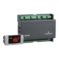
CX660 and CH660 keyboard
Housing: self extinguishing PC+ABS.
Case: CX660 facia 35x77 mm; depth 18mm; CH660 facia 38x80 mm; depth 18mm
Mounting: panel mounting in a 29x71 mm panel cut-out
Protection: IP20; Frontal protection: IP65
Power supply: from XM600K power module
Display: 3 digits, red LED, 14,2 mm high
Optional output: buzzer
Power modules
Housing: 8 DIN
Power supply: depending on the model 110Vac
85% (no condensing)
Resolution: 0,1 °C or 1°C or 1 °F (selectable)
Measuring and regulation range:
NTC / NTC-US probe: -40÷110°C (-58÷230°F).
PTC probe: -50÷150°C (-67 ÷ 302°F)
Pt1000 probe: -100 ÷ 100°C (-148 ÷ 212°F)
Accuracy (ambient temp. 25°C): ±0,5 °C ±1 digit
Digital inputs: 3 free of voltage
Inputs: up to 4 NTC/PTC/Pt1000 probes
Serial output: RS485 with ModBUS - RTU and LAN
Relay outputs: Total current on loads MAX. 16A
Solenoid Valve: relay SPST 5(3) A, 250Vac
defrost: relay SPST 16 A, 250Vac
fan: relay SPST 8 A, 250Vac
light: relay SPST 16 A, 250Vac
alarm (XM670K): SPDT relay 8 A, 250Vac
Aux (XM670K): SPST relay 8 A, 250Vac
Optional output (AnOUT) DEPENDING ON THE MODELS:
• PWM / Open Collector outputs: PWM or 12Vdc max 40mA
• Analog output: 4÷20mA or 0÷10V
Purpose of control: operating control
Construction of control: incorporated control, intended to be used in Class I or Class II equipment.
 Loading...


