1592038030 XR70CH GB r1.0 29.05.2014 XR70CH 3/5
FANS
Fans operating mode: (C-n; o-n; C-Y; o-Y) C-n = runs with the compressor, OFF during
defrost; o-n = continuous mode, OFF during defrost; C-Y = runs with the compressor,
ON during defrost; o-Y = continuous mode, ON during defrost.
Fans delay after defrost: (0 to 255min) interval between end of defrost and evaporator
fans start.
Temperature differential to avoid fan short cycles: (0 to 59°C; 0 to 90°F) (N.B.: if
FCt=0 function disabled) if the difference of temperature between the evaporator and the
room probes is higher than FCt value, the fans will be switched on.
Fans stop temperature: (-55 to 50°C; -67 to 122°F) setting of temperature, detected by
evaporator probe, above which fans are always OFF.
Fan ON time: (0 to 15min) with Fnc=C_n or C_Y, (fan activated in parallel with
compressor) it sets the evaporator fan ON cycling time when the compressor is off. With
Fon=0 and FoF≠0 the fan are always off, with Fon=0 and FoF=0 the fan are always off.
Fan OFF time: (0 to 15min) With FnC=C_n or C_Y, (fan activated in parallel with
compressor) it sets the evaporator fan off cycling time when the compressor is off.
With Fon=0 and FoF≠0 the fan are always off, with Fon=0 and FoF=0 the fan are
always off.
Probe selection for fan management: (nP; P1; P2; P3; P4) nP = no probe;
P1 =thermostat probe; P2 = evaporator probe; P3 =configurable probe; P4 = Probe on
Hot Key plug.
ALARMS
Temperature alarms configuration: (Ab; rE) Ab = absolute temperature, alarm
temperature is given by the ALL or ALU values. rE = temperature alarms are referred to
the set point. Temperature alarm is enabled when the temperature exceeds the
[SET+ALU] or [SET-ALL] values.
MAXIMUM temperature alarm:
If ALC=Ab: [ALL to 150.0°C or ALL to 302°F]
If ALC=rE: [0.0 to 50.0°C or 0 to 90°F]
when this temperature is reached the alarm is enabled, after the ALd delay time.
Minimum temperature alarm:
If ALC=Ab: [-100°C to ALU; -148 to ALU]
If ALC=rE: [0.0 to 50.0°C or 0 to 90°F]
when this temperature is reached the alarm is enabled, after the ALd delay time.
Differential for temperature alarm recovery: (0.1 to 25.5°C; 1 to 45°F) intervention
differential for recovery of temperature alarm.
Temperature alarm delay: (0 to 255 min) time interval between the detection of an
alarm condition and alarm signalling.
Exclusion of temperature alarm at start-up: (0.0 to 24h00min, res. 10min) time
interval between the detection of the temperature alarm condition after instrument power
on and alarm signalling.
CONDENSER TEMPERATURE ALARM
Probe selection for temperature alarm of condenser: (nP; P1; P2; P3; P4)
nP = no probe; P1 = thermostat probe; P2 = evaporator probe; P3 = configurable probe;
P4 = Probe on Hot Key plug.
Low temperature alarm of condenser: (-100 to 150°C; -148 to 302°F) when this
temperature is reached the LA2 alarm is signalled, possibly after the Ad2 delay.
High temperature alarm of condenser: (-100 to 150°C; -148 to 302°F) when this
temperature is reached the HA2 alarm is signalled, possibly after the Ad2 delay.
Differential for temperature condenser alarm recovery: 0.1 to 25.5°C; 1 to 45°F
Condenser temperature alarm delay: (0 to 255 min) time interval between the
detection of the condenser alarm condition and alarm signalling.
Condenser temperature alarm exclusion at start up: 0.0 to 24h00min, res. 10min.
Compressor off with low temperature alarm of condenser: (n; Y) n = compressor
keeps on working; Y = compressor is switched off till the alarm is present, in any case
regulation restarts after AC time at minimum.
Compressor off with high temperature alarm of condenser: (n; Y) n = compressor
keeps on working; Y = compressor is switched off till the alarm is present, in any case
regulation restarts after AC time at minimum.
FOURTH RELAY
Alarm relay silencing (with oA3 =ALr): (n; Y) n = silencing disabled: alarm relay stays
on till alarm condition lasts. Y = silencing enabled: alarm relay is switched OFF by
pressing a key during an alarm.
Second relay configuration (1-4): (dEF; FAn; ALr; LiG; AUS; onF; db; dEF2; HES) dEF
= defrost; FAn = do not select it; ALr = alarm; LiG = light; AUS = Auxiliary relay; onF =
always on with instrument on; db = neutral zone; dEF2 = do not select it; HES = night
blind.
Alarm relay polarity: (CL; oP) it set if the alarm relay is open or closed when an alarm
occurs. CL = terminals 1-4 closed during an alarm; oP = terminals 1-4 open during an
alarm.
DIGITAL INPUTS
Second digital input polarity: (oP; CL) oP = the digital input is activated by opening the
contact; CL = the digital input is activated by closing the contact.
Second digital input configuration: (EAL; bAL; PAL; dor; dEF; ES; AUS; Htr; FAn;
HdF; onF) EAL = external alarm: “EA” message is displayed; bAL = serious alarm “CA”
message is displayed; PAL = pressure switch alarm, “CA” message is displayed; dor =
door switch function; dEF = activation of a defrost cycle; ES = energy saving; AUS =
auxiliary relay activation with oA3=AUS; Htr = type of inverting action (cooling or
heating); FAn = fan; HdF = Holiday defrost (enable only with RTC); onF = to switch the
controller off.
Digital input 1 alarm delay: (0 to 255 min) delay between the detection of the external
alarm condition and its signalling.
When i1F= PAL, it is the interval of time to calculate the number of pressure switch
activation.
Number of pressure switch activation: (0 to 15) Number of activation, during the did
or d2d interval, before signalling an alarm event (i1F, i2F=PAL).
If the nPS activation during did or d2d time is reached, switch off and on the instrument
to restart normal regulation.
Compressor status when open door: (no; FAn; CPr;F_C;) no = normal;
FAn = normal; CPr = compressor OFF, F_C = compressor OFF.
Outputs restart after door open alarm: (n; Y) n = outputs follow the odC parameter.
Y = outputs restart with a door open alarm.
Delta temperature during an Energy Saving cycle: (-30.0 to 30.0°C; -54 to 54°F) it
sets the increasing value of the set point [SET+HES] during the Energy Saving cycle.
OTHER
Serial address: (1 to 247) identifies the instrument address when connected to a
ModBUS compatible monitoring system.
Type of probe: (PtC; ntC) it allows to set the kind of probe used by the instrument:
PtC = PTC probe, ntC = NTC probe.
On/Off key enabling: (nU; oFF; ES) nU = disabled; oFF = enabled; ES = not set it.
Thermostat probe display.
Evaporator probe display.
Third probe display- optional.
Real set point: it shows the set point used during the energy saving cycle or during the
continuous cycle.
Software release for internal use.
Parameter table code: readable only.
8. DIGITAL INPUTS
The free voltage digital input is programmable by the i1F parameter.
8.1 GENERIC ALARM (I1F = EAL)
As soon as the digital input is activated the unit will wait for did time delay before signalling the EAL
alarm message. The outputs statuses don’t change. The alarm stops just after the digital input is de-
activated.
8.2 SERIOUS ALARM MODE (I1F = BAL)
When the digital input is activated, the unit will wait for did delay before signalling the CA alarm
message. The relay outputs are switched OFF. The alarm will stop as soon as the digital input is de-
activated.
8.3 PRESSURE SWITCH (I1F = PAL)
If during the interval time set by did parameter, the pressure switch has reached the number of
activation of the nPS parameter; the CA pressure alarm message will be displayed. The compressor
and the regulation are stopped. When the digital input is ON the compressor is always OFF. If the
nPS activation in the did time is reached, switch off and on the instrument to restart normal
regulation.
8.4 DOOR SWITCH INPUT (I1F = DOR)
It signals the door status and the corresponding relay output status through the odC parameter:
no = normal (any change); FAn = Fan OFF; CPr = Compressor OFF; F_C = Compressor and fan
OFF. Since the door is opened, after the delay time set through parameter doA, the door alarm is
enabled, the display shows the message dA and the regulation restarts is rtr=YES. The alarm stops
as soon as the external digital input is disabled again. With the door open, the high and low
temperature alarms are disabled.
8.5 START DEFROST (I1F = DEF)
It starts a defrost if there are the right conditions. After the defrost is finished, the normal regulation will
restart only if the digital input is disabled otherwise the instrument will wait until the “MdF” safety time
is expired.
8.6 SWITCH THE AUXILIARY RELAY (I1F = AUS)
With oA3 = AUS the digital input switched the status of the auxiliary relay
8.7 INVERSION OF THE KIND OF ACTION: HEATING-COOLING (I1F=HTR)
This function allows to invert the regulation of the controller: from cooling to heating and viceversa.
8.8 ENERGY SAVING (I1F = ES)
The Energy Saving function allows to change the set point value as the result of the SET+ HES
(parameter) sum. This function is enabled until the digital input is activated.
8.9 ON OFF FUNCTION (I1F = ONF)
To switch the controller on and off.
8.10 DIGITAL INPUT POLARITY
The digital input polarity depends on the i1P parameter.
i1P = CL: the input is activated by closing the contact.
i1P = oP: the input is activated by opening the contact
9. TTL SERIAL LINE – FOR MONITORING SYSTEMS
The TTL serial line, available through the HOT KEY connector, allows to connect the instrument to a
monitoring system ModBUS-RTU compatible such as the XWEB500.
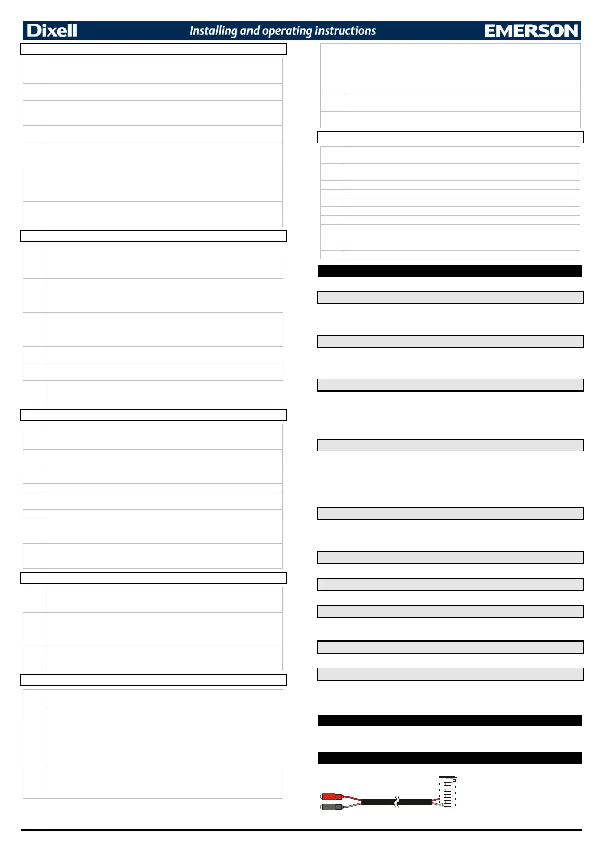
10. X-REP OUTPUT – OPTIONAL
As optional, an X-REP can be connected to the instrument, trough the dedicated connector.
To connect the X-REP to the instrument the
following connectors must be used CAB-
51F(1m), CAB-52F(2m), CAB-55F(5m),

 Loading...


