MODBUS Termination Blocks Default Setting Values • 27
dtE Defrost termination temperature
[-50 to 50°C]
[-50 to 122°F]
[8°C]
[46°F]
Pr1
idF Interval between defrost cycles 1 to 120 hours 6 Pr1
MdF (Maximum) length for defrost 0 to 255 min 30 Pr1
dSd Start defrost delay 0 to 99 min 0 Pr2
dFd Displaying during defrost rt, it, SEt, DEF it Pr2
dAd MAX display delay after defrost 0 to 255 min 30 Pr2
Fdt Draining time 0 to 120 min 0 Pr2
dPo First defrost after start-up n=after idF; Y=immed. n Pr2
dAF Defrost delay after fast freezing 0 to 24h 00min, res. 10min 0.0 Pr2
FnC Fan operating mode C-n; o-n; C-Y; o-Y o-n Pr1
Fnd Fan delay after defrost 0 to 255 min 10 Pr1
FCt
Differential of temperature to force
fan activation
[0 to 50°C]
[0 to 90°F]
[10°C]
[10°F]
Pr2
FSt Fan stop temperature
[-50 to 50°C]
[-58 to 122°F]
[36°C]
[23°F]
Pr1
Fon Fan on time with compressor off 0 to 15 min 0 Pr2
FoF Fan off time with compressor off 0 to 15 min 0 Pr2
FAP Probe selection for fan management nP; P1; P2; P3; P4 P2 Pr2
ACH Kind of action for auxiliary relay CL; Ht CL Pr2
SAA Setpoint for auxiliary relay
[-50 to 110°C]
[-58 to 230°F]
[0.0°C]
[32°F]
Pr2
SHY Differential for auxiliary relay
[0.1 to 25.5°C]
[1 to 45°F]
[2.0°C]
[2°F]
Pr2
ArP Probe selection for auxiliary relay nP; P1; P2; P3; P4 nP Pr2
Sdd
Auxiliary relay operating during
defrost
n; Y n Pr2
ALP Alarm probe selection nP; P1; P2; P3; P4 P1 Pr2
ALC Temperat. alarms configuration
rE= related to set;
Ab = absolute
Ab Pr2
ALU MAXIMUM temperature alarm
[SEt to 110.0°C]
[SEt to 230°F]
[110°C]
[230°F]
Pr1
ALL Minimum temperature alarm
[-50°C to SEt]
[-58°F to SEt]
[-50.0°C]
[-58°F]
Pr1
AFH
Differential for temperat. alarm
recovery
[0.1°C to 25.5°C]
[1°F to 45°F]
[2.0°C]
[2°F]
Pr2
ALd Temperature alarm delay 0 to 255 min 15 Pr2
dAo Delay of temperature alarm at start up 0 to 24h 00min, res. 10min 1.3 Pr2
AP2
Probe for temperat. alarm of
condenser
nP; P1; P2; P3; P4 P4 Pr2
AL2 Condenser for low temperat. alarm
[-50 to 110°C]
[-58 to 230°F]
[-40.0°C]
[-40°F]
Pr2
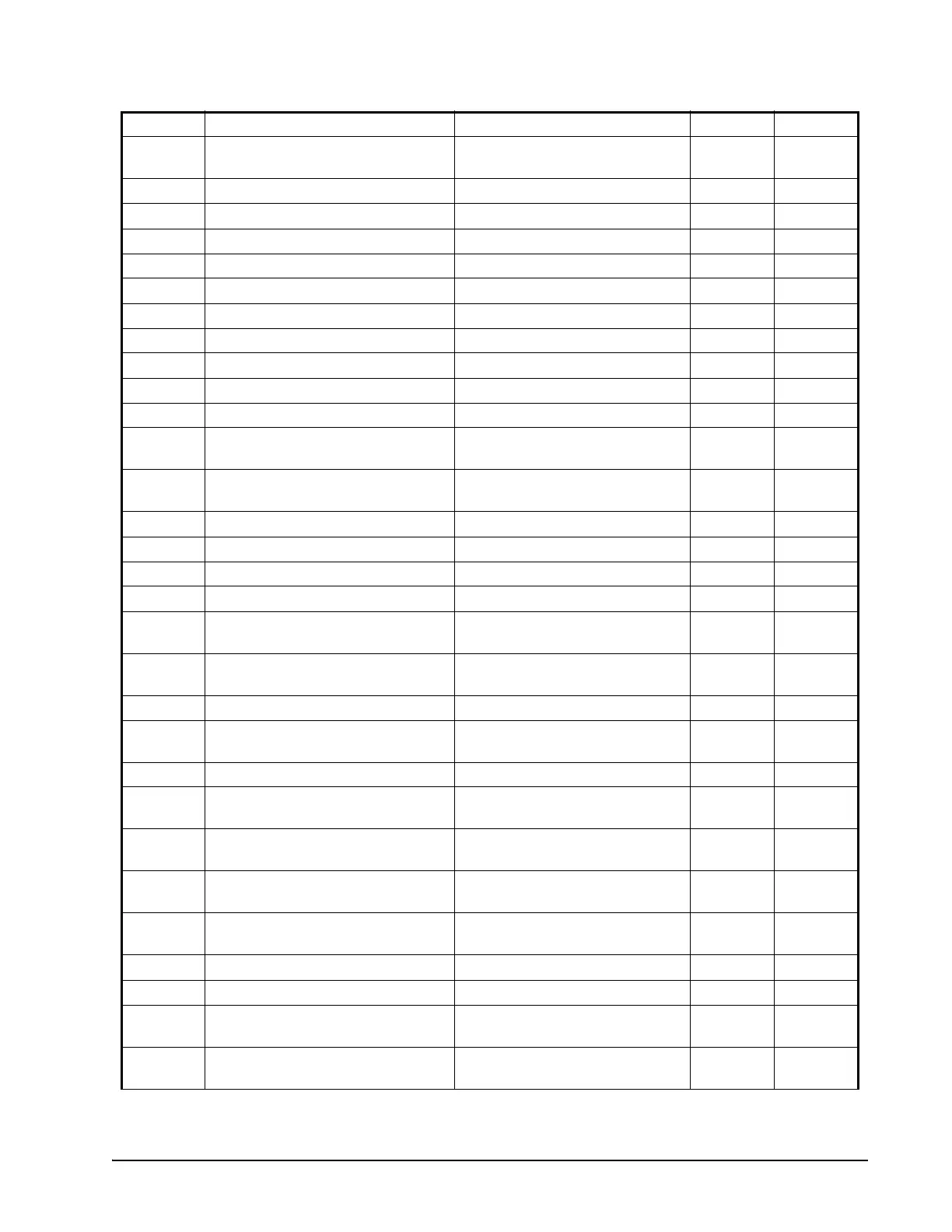
Label Name Range Value Level
Table 19-1- XR75CX Default Setting Values (
2
Only for XR75CX with X-REP output)

 Loading...