4
English
ATEX Reference Guide EL Electric actuators
DOC.ATX.EL.1 Rev.: C
February 2012
2.4 Special ATEX conditions for safe use
1 Ambient temperature range: -20° to +60°C
Cable and cable glands compatible
with a temperature of 130°C
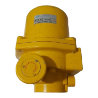
II 2 G Ex db IIB T4
Serial No.:
Year of manufacturing:
Emerson, 7556BR Hengelo NL
0344
EL 150
240
0.5
50
Type:
U:
I:
f:
V
A
Hz
DEKRA 12ATEX0001 X
2 Contact Emerson for information with regard to
dimensions of the ame proof joints.
Actuator size
Power supply
specications
Ex db Flame
proof version
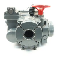
2 Identication
2.1 Weather proof execution
* Actuator must be isolated electronically before any
(dis)assembly is begun.
* Before mounting or (dis)assembling the actuator
consult the relevant sections of this manual.
TYPE
SERIAL No.
WWW.EL-O-MATIC.COM
EL XXXX XXXXX XXXXX
XXXXXXXXXXXXXX
TM
2.2 ATEX approved execution
WARNING
* The ATEX ame proof certied EL electric actuator
is a Group II category 2 equipment and intended
for use in areas in which explosive atmospheres
caused by mixtures of air and gases, vapors or
mists are likely to occur.
Therefore the ATEX ame proof certied electric
actuator may be used in (ATEX) classied Zones 1
& 2 (Gases)
2.3 ATEX Installation instructions
1 The cable entry device and the closing elements of
unused apertures must be of a certied ameproof
type, suitable for the conditions of use and correctly
installed.
2 Heat resistant cable and cable glands shall be
used, suitable for temperatures of at least 130°C.
3 When the EL actuator is connected to a separate
source of heating or cooling, such as a heated or
cooled process vessel or pipeline, the temperature
transfer should not cause the actuator to exceed the
specied ambient temperature range (Tamb = -20
°C ... +60 °C).
4 Wiring dimensions for external earth connection is
4mm² (12 AWG), for internal earth connection max.
2.5mm² (22-12AWG)
5 Blind plugs or cable gland shall be engaged into the
cable entries minimal 5 threads.
6 When replacing cover screws, use cover screws
according ISO 3506 with property class A2-70.
Actuator size
Power supply specications
Electrical entry dimensions
 Loading...