Do you have a question about the Emerson EXD-SH1 and is the answer not in the manual?
Superheat control, temperature control, low pressure switch, freeze protection. Controls two valves independently.
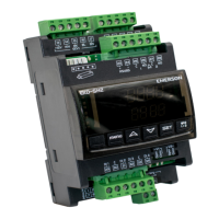
Kits include all components for setup in one box, featuring integrated keyboard, two-line display, and plug-in terminals.
Connect via Modbus to monitoring systems, including Emerson's E2 system controller.
User responsibility to pass waste electrical and electronic equipment to a designated collection point for safe recycling.
Refer to the electrical wiring diagram for electrical connections. Keep controller and sensor wiring separated from supply power cables.
Read instructions thoroughly. Disconnect all voltages before installation/service. Ensure all connections are complete.
Explanation of terminal connections for EXD-SH1/SH2 with UPS or Supercap modules, including circuit and component identification.
Use class II transformers, do not ground 24VAC lines, and use individual transformers to avoid interference and grounding issues.
Steps for initial system setup, including vacuuming the circuit and charging the system with refrigerant after valve closure.
Instructions for setting essential parameters like password, function type, refrigerant, and sensor types before system startup.
Description of controller display elements, button functions, and modes for parameter setting and instant value display.
Procedure for manual valve control for service or maintenance, including setting parameters for manual mode and valve opening.
Comprehensive list of controller parameters, their codes, descriptions, min/max values, and factory settings for EXD-SH1 and EXD-SH2.
Table showing default MOP saturation temperatures for various refrigerants, aiding in setting the Maximum Operating Pressure function.
Factory settings for control valve startup behavior based on valve type (EX4/EX7/EX8/CV) and timing specifications.
List of alarm codes, their related parameters, alarm relay behavior, required actions, and whether the alarm requires manual resolution.
Common symptoms, their potential causes, and recommended actions for troubleshooting controller and system operation issues.
| Brand | Emerson |
|---|---|
| Model | EXD-SH1 |
| Category | Controller |
| Language | English |