2
850 and 950 Series
North America Only
Specications
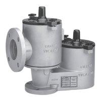
The Specications section on this page provides specications for the 850 and 950 Series pressure/vacuum relief
valve. Specication is stamped on the nameplate attached to the relief valve. Refer to Product Identication and
Marking section for the nameplate details.
Available Construction
See Figures 3 and 4
Inlet Connection Sizes
2 through 12 in. / 50 through 300 mm
Pressure Ranges
(1)(2)
0.4 to 32 oz./sq.in.
1.0 to 55.0 in. w.c.
1.72 to 138 mbar
17.6 to 1406 mm w.c.
Vacuum Pressure Ranges
(1)(2)
0.4 to 32.0 oz/sq. in.
1.0 to 55.0 in. w.c.
1.72 to 138 mbar
17.6 to 1406 mm w.c.
Construction Materials
Housing: Aluminum, Ductile iron, Stainless steel
or Carbon steel
Seat / Pallet: Polyphenylene Sulde (PPS) or
316 Stainless steel
Pallet Seal: Buna-N, FEP Teon
®
or Viton
®
Hardware: Zinc-plated Carbon steel or
Stainless steel
Weights: Zinc-plated Carbon steel, Stainless steel
or Lead
Gaskets: Buna-N, Teon
®
or Viton
®
Certication
EN 13463-1: 2001
EN 13463-5: 2003
1. The pressure limits in this Instruction Manual and any applicable standard or code limitation should not be exceeded.
2. Pressure or vacuum setting has an increment of 0.5 oz./sq.in., 0.5 in. w.c. or 2.2 mbar.
Model - Inlet Size x Outlet Size - Housing Material Pallet and Seat Material Pallet Seal Material Body/Seat/Lid Seal Material -
850 2 to 12 in. 3 to14 in. 1 = Aluminum
2 = Ductile Iron
4 = 316SST
5 = Carbon Steel
1 = PPS Polyphenylene Sulfide
2 = 316SST
1 = FEP
2 = Nitrile (NBR)
3 = Fluorocarbon (FKM)
1 = PTFE Body and FEP
Seat/Lid
2 = Nitrile (NBR)
3 = Fluorocarbon (FKM)
Pressure Units Pressure Setting / Vacuum Units Vacuum Setting - Weight Material - Options
z = oz./sq.in.
n = in. w.c.
mm = mm w.c.
mb = mbar
0.5 to 32.0 oz./sq.in.
0.86 to 55.0 in. w.c.
22 to 1406 mm w.c.
2.2 to 138 mbar
z = oz./sq.in.
n = in. w.c.
mm = mm w.c.
mb = mbar
0.5 to 32.0 oz./sq.in.
0.86 to 55.0 in. w.c.
22 to 1406 mm w.c.
2.2 to 138 mbar
C = CS ZP
S = SST
L = Lead
0 = No Options
F = Flat Face Flange (standard for Alumunim)
R = Raised Face Flange (standard for CS, DI, SS)
X = Epoxy Coating
W1 = Wireless Pressure and Vacuum Monitoring
W2 = Wireless Pressure Monitoring Only
W3 = Wireless Vacuum Monitoring Only
W4 = Wired Pressure and Vacuum Monitoring
W5 = Wired Pressure Monitoring Only
W6 = Wired Vacuum Monitoring Only
MODEL 850 PRESSURE/VACUUM RELIEF VALVE MODEL NUMBER
MODEL 950 PRESSURE/VACUUM RELIEF VALVE MODEL NUMBER
Model - Inlet Size - Housing Material Pallet and Seat Material Pallet Seal Material Body/Seat/Lid Seal Material
-
950 2 to 12 in. 1 = Aluminum
2 = Ductile Iron
4 = 316SST
5 = Carbon Steel
1 = PPS Polyphenylene Sulfide
2 = 316SST
1 = FEP
2 = Nitrile (NBR)
3 = Fluorocarbon (FKM)
1 = PTFE Body and FEP Seat/Lid
2 = Nitrile (NBR)
3 = Fluorocarbon (FKM)
Pressure Units Pressure Setting / Vacuum Units Vacuum Setting - Weight Material - Options
z = oz./sq.in.
n = in. w.c.
mm = mm w.c.
mb = mbar
0.5 to 32.0 oz./sq.in.
0.86 to 55.0 in. w.c.
22 to 1406 mm w.c.
2.2 to 138 mbar
z = oz./sq.in.
n = in. w.c.
mm = mm w.c.
mb = mbar
0.5 to 32.0 oz./sq.in.
0.86 to 55.0 in. w.c.
22 to 1406 mm w.c.
2.2 to 138 mbar
C = CS ZP
S = SST
L = Lead
0 = No Options
F = Flat Face Flange (standard for Alumunim)
R = Raised Face Flange (standard for CS,DI, SS)
X = Epoxy Coating
W1 = Wireless Pressure and Vacuum Monitoring
W2 = Wireless Pressure Monitoring Only
W3 = Wireless Vacuum Monitoring Only
W4 = Wired Pressure and Vacuum Monitoring
W5 = Wired Pressure Monitoring Only
W6 = Wired Vacuum Monitoring Only
Figure 3. Pressure/Vacuum Relief Valve Model Number
Teon
®
and Viton
®
are marks owned by E. I. du Pont de Nemours and Company.
 Loading...


