1-6-2 H9600DC
Reference Notes
CAUTION 1: Locking Tabs (L-1) and (L-2) are fragile.
Be careful not to break them.
1-1. Release three Locking Tabs (L-1).
1-2. Release three Locking Tabs (L-2), then remove
the Front Assembly.
CAUTION 2: Electrostatic breakdown of the laser
diode in the optical system block may occur as a
potential difference caused by electrostatic charge
accumulated on cloth, human body etc, during
unpacking or repair work.
To avoid damage of pickup follow next procedures.
2-1. Disconnect Connector (CN301). Remove a
Screw (S-6) and lift the DVD Main CBA Unit. (Fig.
D4)
2-2. Short the three short lands of FPC cable with sol-
der before removing the FFC cable (CN201) from
it. If you disconnect the FFC cable (CN201), the
laser diode of pickup will be destroyed. (Fig. D4)
CAUTION 3: When reassembling, confirm the FFC
cable (CN201) is connected completely. Then remove
the solder from the three short lands of FPC cable.
(Fig. D4)
4. When reassembling, solder wire jumpers as shown
in Fig. D6.
5. Before installing the Deck Assembly, be sure to
place the pin of LD-SW on Main CBA as shown in
Fig. D6. Then, install the Deck Assembly while
aligning the hole of Cam Gear with the pin of LD-
SW, the shaft of Cam Gear with the hole of LD-SW
as shown in Fig. D6.
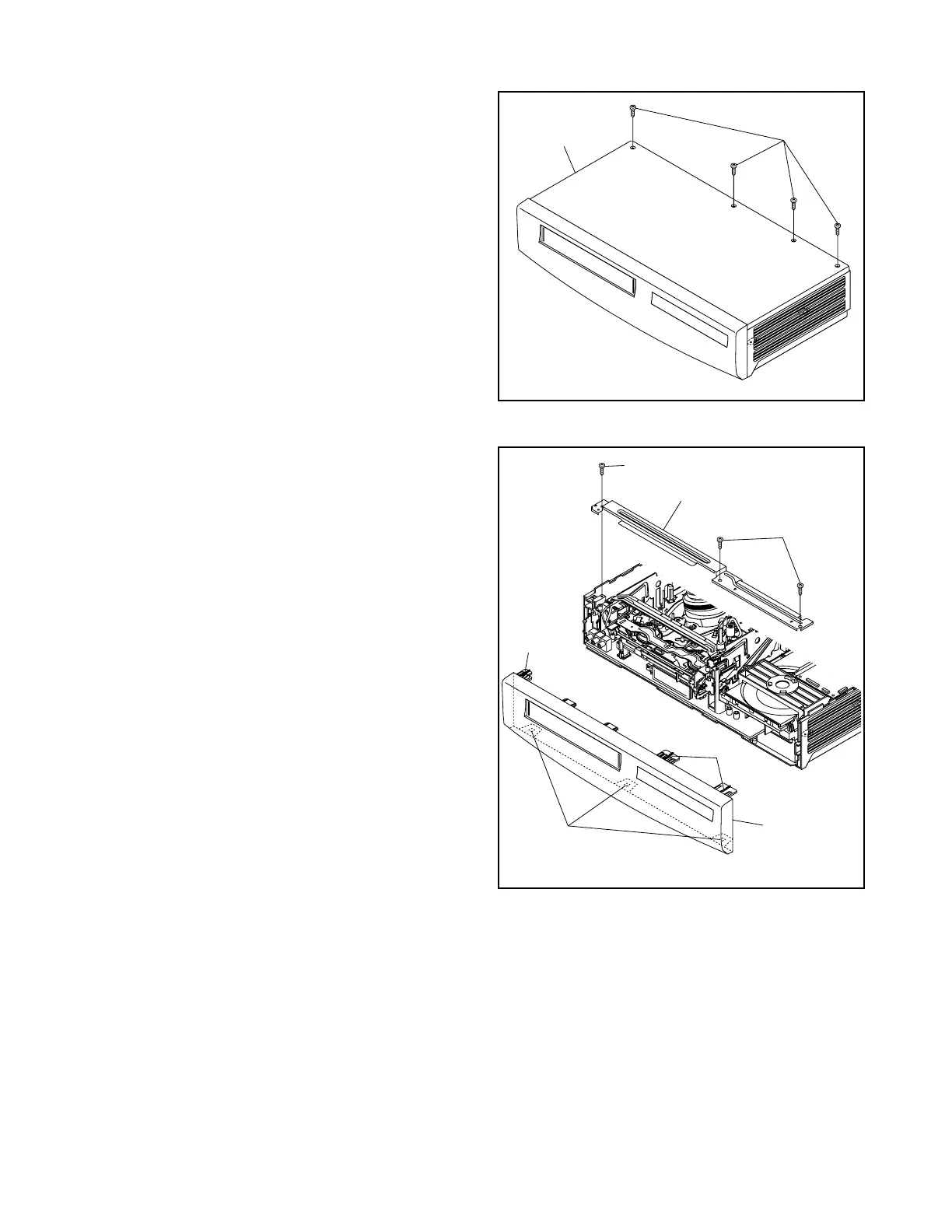
(S-1)
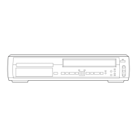
[1] Top Case
Fig. D1
(S-2)
(S-2)
(L-1)
(L-2)
(L-1)
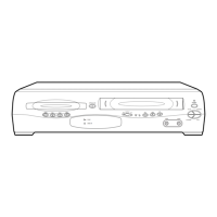
[2] Front
Assembly
[3] Top Blacket
Fig. D2
 Loading...