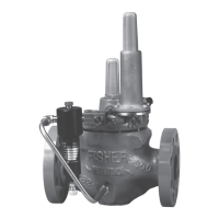
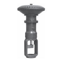
Types 1098-EGR and 1098H-EGR
2
Body Sizes and End Connection Styles
See Table 1
Main Valve Maximum Inlet Pressure
(1)
400 psig / 27.6 bar or body rating limit
whichever is lower
Maximum Pilot Supply Pressure
(1)(2)
600 psig / 41.4 bar
Outlet Pressure Ranges
See Table 2
Actuator Sizes and Maximum Pressures
See Table 3
Maximum and Minimum Differential Pressures
See Table 4
Main Valve Flow Characteristic
Linear (standard), Whisper Trim
™
or
Quick opening
1. The pressure/temperature limits in this Instruction Manual or any applicable standard limitation should not be exceeded.
2. For stability or overpressure protection, a reducing regulator may be installed upstream of the pilot according to the Installation section.
The Specications section lists pressure limitations and other specications for various Types 1098-EGR and
1098H-EGR constructions. Specications for a given regulator as it originally comes from the factory are stamped
on nameplates located on both the actuator and main valve body, while the pilot control spring range is displayed
on the pilot spring case and the pilot restriction code is stamped on the pilot body (S = standard gain, L = low gain
and H = high gain). To determine maximum pressure ratings, the individual ratings for the main valve, actuator and
pilot must all be considered.
Main Valve Flow Direction
In through the seat ring and out through the cage
Pressure Registration
External
Temperature Capabilities
(1)
Nitrile (NBR):
-20 to 180°F / -29 to 82°C
Fluorocarbon (FKM):
0 to 300°F / -18 to 149°C,
Water is limited to 0 to 200°F / -18 to 93°C
Ethylenepropylene (EPDM):
-20 to 275°F / -29 to 135°C
Options
• NACE Construction
• Boiler Fuel Construction
• Aqueous Service Construction
• Monitor Conguration
• Noise Abatement Trim
Table 1. Body Sizes and End Connection Styles
BODY SIZE
CAST IRON STEEL OR STAINLESS STEEL
NPS DN
1 or 2 25 or 50 NPT, CL125 FF or CL250 RF NPT, CL150 RF, CL300 RF, CL600 RF, BWE, SWE or PN 16/25/40
3, 4 or 6 80, 100 or 150 CL125 FF or CL250 RF CL150 RF, CL300 RF, CL600 RF, BWE or PN 16/25/40
8 x 6 or 12 x 6 200 x 150 or 300 x 150 - - - - CL150 RF, CL300 RF, CL600 RF or BWE

 Loading...

