www.Fisher.com
Fisher
™
2502 Controllers
Contents
Introduction 2.................................
Scope of Manual 2.............................
Description 2.................................
Specifications 2...............................
Educational Services 2.........................
Installation 4..................................
249 Sensors 5................................
Uncrating 5..................................
Controller Orientation 6........................
Controller‐Sensor Action 6......................
Mounting Caged Sensors 7.....................
Mounting Cageless Sensors 9...................
Side‐Mounted Sensor 9.....................
Top‐Mounted Sensor 10....................
Supply Pressure 11............................
Prestartup Checks 12...........................
Adjustments 13...............................
Level Set Adjustment 13....................
Proportional Band Adjustment 13............
Reset Adjustment 14.......................
Differential Relief Adjustment 15.............
Calibration 15..................................
Precalibration Requirements 15.................
Wet Calibration 15.........................
Dry Calibration 15.........................
Controller and Torque Tube Arm
Disassembly 16.........................
Determining Suspended Weight
for Calibration 16........................
Calibration Procedure 17.......................
Startup 18.....................................
Principle of Operation 19........................
2502 Controller 21............................
2502F Controller with Reset
Relief Valve 21..............................
Maintenance 22................................
Troubleshooting 23............................
Removing Controller from Sensor 24.............
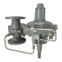
2502 CONTROLLER
249B SENSOR
W8334
Figure 1. Fisher 2502 Controller Mounted on 249B
Sensor
Changing Mounting Method 25.................
Installing Controller on Sensor 26................
Changing Proportional, Reset, or
Differential Relief Valve 27..................
Testing Relay Dead Band 27.....................
Changing Relay 27.............................
Replacing Bellows 27..........................
Reversing Action 28...........................
Parts Ordering 29...............................
Parts Kits 29...................................
Parts List 29...................................
Instruction Manual
D200126X012
2502 Controllers
June 2017