Type 310A
12
4.
place the spring (key 36)
in the piston guide (key 23). Install the piston,
and secure with the retaining ring (key 27).
place the
spring (key 36 - working pilot) or spacer
(key 53 - monitoring pilot) in the piston guide.
Install the piston and secure it in the piston guide
with the retaining ring (key 27).
5. Install the O-ring (key 13) on the piston seat
assembly (key 28), and screw the assembly into
the piston guide.
6. Install the piston guide in the pilot body (key 22).
7. Insert the bleed valve (key 20) through the bleed
valve seat (key 19).
8. Install the spring (key 35) and valve disk assembly
(key 18) onto the bleed valve (key 20).
9. Place the above assembly in the yoke (key 16),
and screw on the adaptor (key 17).
10. Place the diaphragm (key 9), diaphragm plate
(key 8), and sealing washer (key 15) on the yoke,
and secure with the cap screw (key 10).
11. Place the other diaphragm, diaphragm plate,
and sealing washer on the adaptor, and secure
with the nut (key 21).
12. Insert this entire assembly through the
diaphragm spacer (key 11) until the outer edges
of both diaphragms are in place on the spacer.
13. Fit the O-rings (key 14) on the orice assembly
(key 12).
14. Rotate the yoke to receive the orice assembly.
15. Place entire assembly on the pilot body (key 22).
16. Apply lubricant to cap screws (key 6). Insert
the cap screws in the spring case (key 1) and
pilot body, and tighten the cap screws to 25 to
30 foot-pounds (34 to 41 N•m).
17. If removed, install the spring seats (key 5) and
the control spring (key 37).
18. Install the cover gasket (key 7), spring case cap
(key 2), adjusting screw (key 3), and locknut
(key 4).
19. Install the pilot into the main valve using the pipe
nipple (not shown).
20. Connect the loading tubing from the male elbow
on the base body (key 2, Figures 10 and 11) to
the connector on the side of the pilot. Refer to
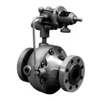
Figure 1 for the assembled location of the tubing,
elbow, and connector.
This procedure describes how to completely
disassemble and assemble a main valve. When
inspection or repairs are required, disassemble only
those parts necessary to accomplish the job; then start
the assembly at the appropriate step. Key numbers
are referenced in Figures 10 and 11.
Disassembly
1. Disconnect the loading tubing from the connection
in the base body (key 2). Disconnect the
downstream pressure control line from
the connection in the case body (key 1) and the
external supply line from the pilot.
2. Remove the main valve from the pipeline.
3. Remove the cap screws (key 14), and separate
the case body (key 1) from the base body (key 2).
 Loading...

