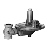
Type 310A
6
Installation
A Type 310A-32A regulator bleeds no gas to
atmosphere during normal operation, thus making
the regulator suitable for installation in pits and
other enclosed locations without elaborate venting
systems. This regulator also can be installed in pits
subject to ooding by venting the pilot spring case
above the expected ood level so that the pilot setting
can be referenced to atmospheric pressure.
1. Use qualied personnel when installing,
maintaining, or operating this regulator. Inspect
the regulator and the pipeline to be certain both
are free of foreign materials.
2. Install the regulator so that the ow arrow cast
on the main valve matches the ow direction of
process uid through the regulator.
3. Apply pipe compound to the male pipeline
threads before installing a regulator with NPT
end connections. Use gaskets between pipeline
and regulator anges when installing a regulator
with anged end connections.
!
4. A Type 32A pilot has a 1/4 NPT vent connection
in the spring case. To remotely vent gas from
the spring case, remove the screened vent, and
connect 1/4-inch (6,4 mm) piping or tubing to the
spring case connection.
The piping or tubing should vent to a safe
location, have as few elbows as possible,
and have a screened vent on its exhaust. Install
the regulator and any remote vent piping or tubing
so that the vent is protected from condensation,
freezing, or any substance that could clog it.
5. Connect a pilot supply line from the upstream
piping to the 1/4 NPT pilot inlet.
6. Connect a downstream control line to a
straight run of pipe 6 to 10 pipe diameters from
the regulator outlet as shown in Figure 6. If
such a distance is not practical, connect the
control line away from elbows, swages, nipples,
or any area where abnormal ow velocities occur.
Figure 6. Typical Pressure Reducing Installation
24B4134
B2444
 Loading...

