Type 310A
2
1. The pressure/temperature limits in this Instruction Manual or any applicable standard limitation should not be exceeded.
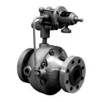
Type 310A main valve with one
Type 32A pilot for standard pressure reducing and
wide-open monitoring applications
Type 310A main valve with
two Type 32A pilots for working monitor applications
NPS 1 body with NPT ends; and NPS 1, 2, 3, 4, or
4 x 6 (DN 25, 50, 80, 100, and 100 x 150) body with
CL300 RF or CL600 RF anged ends
1500 psig (103 bar)
750 psig (51,7 bar)
1425 psig (98,3 bar)
720 psig (49,6 bar)
700 psig (48,3 bar)
800 psig (55,2 bar)
Exceeding this pressure may result in gas venting
from pilot spring case.
1500 psig (103 bar) or
maximum inlet pressure whichever is lower.
See Table 1
15 psig (1,0 bar)
See Table 3
1/4 NPT
-20° to 150°F (-29° to 66°C)
0° to 150°F (-18° to 66°C)
0° to 300°F (-18° to 149°C)
• Main valve body without pilot for on-off service
• Remote-mounted pilot
• Electrically controlled pilot using Type 662 Kixcel™
• Travel indicator
• Pressure loaded pilot
• Type 252 pilot supply lter
• Backpressure protection system
• Restricted Trim (30%, 50%, or 70%)
• NACE construction
• Inlet tap
Table 1. Outlet Pressure Ranges
10 to 20 (0,69 to 1,4) 0.5 (0,03) Silver 1D809627022
10 to 100 (0,69 to 6,9) 2 (0,14) Yellow 1E392527022
100 to 250 (6,9 to 17,2) 5 (0,34) Blue 1D387227022
250 to 600 (17,2 to 41,4) 12 (0,83) Red 1D465127142
400 to 700 (27,6 to 48,3)
(1)
20 (1,4) Green 13A5543X012
1. Available with Nitrile (NBR) pilot diaphragm only.
10 to 20 (0,69 to 1,4) Silver 1D809627022 3.0 (0,21) over normal distribution pressure
10 to 100 (0,69 to 6,9) Yellow 1E392527022 5.0 (0,34) over normal distribution pressure
100 to 250 (6,9 to 17,2) Blue 1D387227022 10 (0,69) over normal distribution pressure
250 to 600 (17,2 to 41,4) Red 1D465127142 15 (1,0) over normal distribution pressure
400 to 700 (27,6 to 48,3) Green 13A5543X012 20 (1,4) over normal distribution pressure
Table 2. Recommended Minimum Differential Between Monitoring Pilot Setting and Distribution Pressure
 Loading...


