Instruction Manual
D100310X012
667 Actuator (Size 30/30i - 76/76i and 87)
May 2018
2
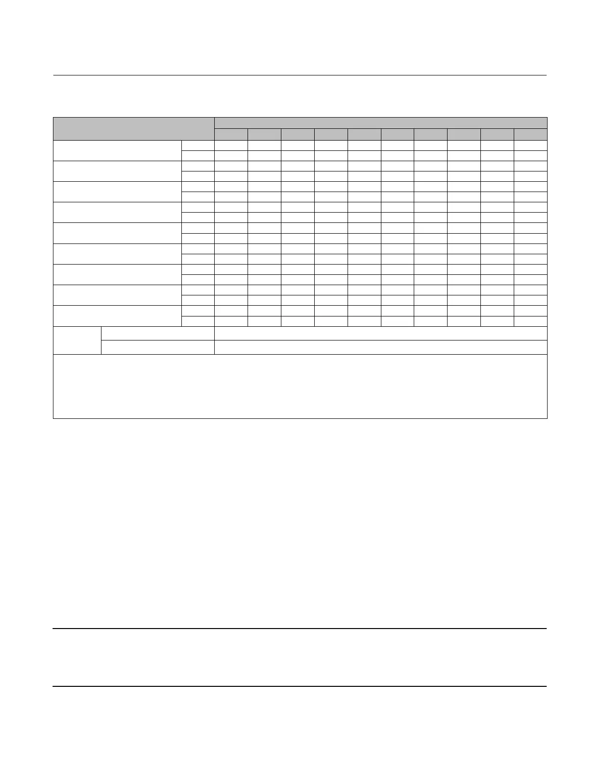
Table 1. Specifications
SPECIFICATION
(1)
ACTUATOR SIZE
30/30i 34/34i 40/40i 45/45i 46/46i 50/50i 60/60i 70/70i
(1)
76/76i 87
(1)
Nominal Effective Area
Sq cm 297 445 445 667 1006 677 1006 1419 1006 1419
Sq Inch 46 69 69 105 156 105 156 220 156 220
Yoke Boss Diameter
mm 54 54 71 71 71 90 90 90 90 125
Inch 2‐1/8 2‐1/8 2‐13/16 2‐13/16 2‐13/16 3‐9/16 3‐9/16 3‐9/16 3‐9/16 5
Acceptable Valve Stem Diameter
mm 9.5 9.5 12.7 12.7 12.7 19.1 19.1 19.1 19.1 25.4
Inch 3/8 3/8 1/2 1/2 1/2 3/4 3/4 3/4 3/4 1
Maximum Allowable Output Thrust
(4)
N 10230 10230 12010 25131 33582 25131 30246 39142 30246 39142
LB 2300 2300 2700 5650 7550 5650 6800 8800 6800 8800
Maximum Travel
(2)
mm 19 29 38 51 51 51 51 76
(3)
51 76
(3)
Inch 0.75 1.125 1.5 2 2 2 2 3
(3)
2 3
(3)
Maximum Casing Pressure for Actuator
Sizing
(4,6)
Bar 3.8 4.8 4.8 4.5 3.8 4.5 3.8 3.4 3.4 3.4
Psig 55 70 70 65 55 65 55 50 50 50
Maximum Excess Diaphragm Pressure
(4,5)
Bar 3.8 1.4 1.4 0.7 0.7 0.7 0.7 0.7 0.7 0.7
Psig 55 20 20 10 10 10 10 10 10 10
Maximum Diaphragm Casing
Pressure
(4,6,7)
Bar 7.6 6.2 6.2 5.2 4.5 5.2 4.5 4.1 4.1 4.1
Psig 110 90 90 75 65 75 65 60 60 60
Approximate Weight
Kg 15/17 22/26 23/26 41/44 55/59 43/48 55/60 115/118 86/89 118
Pounds 34/37 48/58 50/56 90/98 121/129 94/105 122/133 254/260 190/196 260
Material
Temperature
Capabilities
Nitrile Elastomers -40 to 82_C (-40 to 180_F)
Silicone Elastomers -54 to 149_C (-65 to 300_F)
1. These values also apply to the 667‐4 actuator construction.
2. Actuator travel may be less than the value listed after connected to the valve.
3. Maximum actuator travel for 667‐4 is 102 mm (4 inches).
4. See also the Specifications portion of the introduction section.
5. Additional pressure may be added when the actuator is at full travel. If the Maximum Excess Diaphragm Pressure is exceeded, damage to the diaphragm or diaphragm casing might result.
See the Maximum Pressure Limitation section.
6. Maximum diaphragm casing pressure must not be exceeded and must not produce a force on the actuator stem greater than the maximum allowable actuator output thrust or the maxi
mum allowable stem load. See the Maximum Pressure Limitation section.
7. This maximum casing pressure is not to be used for normal operating pressure. Its purpose is to allow for typical regulator supply settings and/or relief valve tolerances.
Description
The 667 actuator (figure 1) and the 667‐4 actuator are reverse‐acting, spring‐opposed diaphragm actuators. They
provide automatic operation of control valves. The 667 actuator provides 76 mm (3 inches) maximum actuator travel.
The 667‐4 actuator provides 102 mm (4 inches) maximum actuator travel. Both actuators position the valve plug in
response to varying pneumatic loading pressure on the diaphragm. Figure 2 shows the operation of these actuators.
A 667 or 667‐4 actuator can be furnished with either a top‐mounted or a side‐mounted handwheel assembly. A
top‐mounted handwheel assembly is normally used as an adjustable down travel stop. (A down travel stop limits
actuator travel in the down direction [when the stem is traveling out of the actuator]. Travel in the up direction is when
the stem is traveling into the actuator.) A side‐mounted handwheel assembly is normally used as an auxiliary manual
actuator. The side‐mounted handwheel can also be used as an adjustable up or down travel stop. Casing‐Mounted
adjustable up or down travel stops are also available on this actuator.
Note
If repeated or daily manual operation is expected, the actuator should be equipped with a side‐mounted handwheel rather than a
casing‐mounted travel stop or top‐mounted handwheel. The side‐mounted handwheel is designed for more frequent use as a
manual operator.

 Loading...


